

Centrifugal rotor
- Summary
- Abstract
- Description
- Claims
- Application Information
AI Technical Summary
Benefits of technology
Problems solved by technology
Method used
Image

Examples
Embodiment Construction
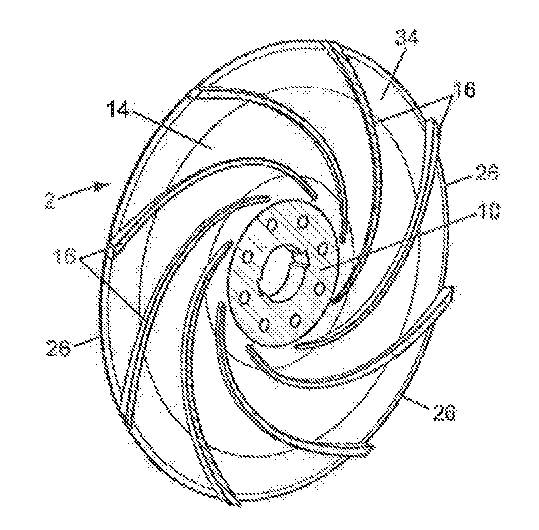
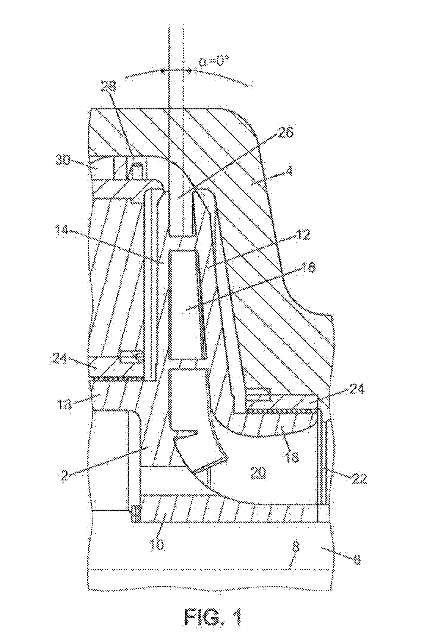
[0027]Those skilled in the art will recognize a centrifugal rotor 2 in FIG. 1 mounted inside a housing 4, for example a compressor housing, and a shaft 6 having a longitudinal axis 8. The following description will be made with reference to a working air compressor (or more generally a gaseous fluid compressor), but this invention may also be applied to pumps for liquids.
[0028]When the centrifugal rotor 2 is rotated by the shaft 6, the air (or other gaseous fluid) is drawn into the centrifugal rotor 2 in a longitudinal direction relative to the longitudinal axis 8, and is driven in a mixed flow motion in the centrifugal rotor 2 while rotating and appear radially with respect to the longitudinal axis 8.
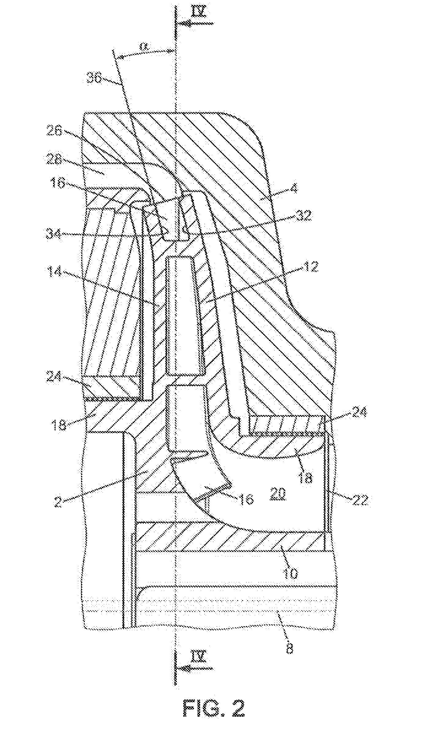
[0029]The centrifugal rotor 2 is built in one piece and comprises a hub 10, a first flange or upstream flange 12, a second flange or downstream flange 14 and vanes 16.
[0030]The hub 10 enables a connection between the shaft 6 and the centrifugal rotor 2. It has an overall circular, cyli...
PUM
 Abstract
Description
Claims
Application Information