Inductive sensor for measuring the position of a shaft of a vehicle

a technology of inductive sensor and vehicle shaft, which is applied in the direction of magnets, magnets, instruments, etc., can solve the problems of limiting the accuracy of the system to the position of each sensor, reducing the complexity and cost of the system, and achieving the effect of simple, reliable and effective solution

Active Publication Date: 2016-05-26
VITESCO TECH GMBH
View PDF5 Cites 2 Cited by
  • Summary
  • Abstract
  • Description
  • Claims
  • Application Information

AI Technical Summary

Benefits of technology

[0007]The invention thus proposes to resolve these disadvantages, at least in part, by proposing a simple

Problems solved by technology

Although such a sensor 1 may be appropriate in the case of an automatic gearbox, it exhibits the disadvantage of determining the position of the shaft in only a single direction X.
However, such a system exhibits a number of disadvantages.
First of all, the use of a matrix of sensors makes it possible to determine the position of the shaft only in a discrete manner, which restricts the accuracy of the system to the position of each sensor.
In addition, the use of a plurality of sensors significantly increases the complexity a

Method used


Image

  • Inductive sensor for measuring the position of a shaft of a vehicle
  • Inductive sensor for measuring the position of a shaft of a vehicle
  • Inductive sensor for measuring the position of a shaft of a vehicle

Examples


Embodiment Construction

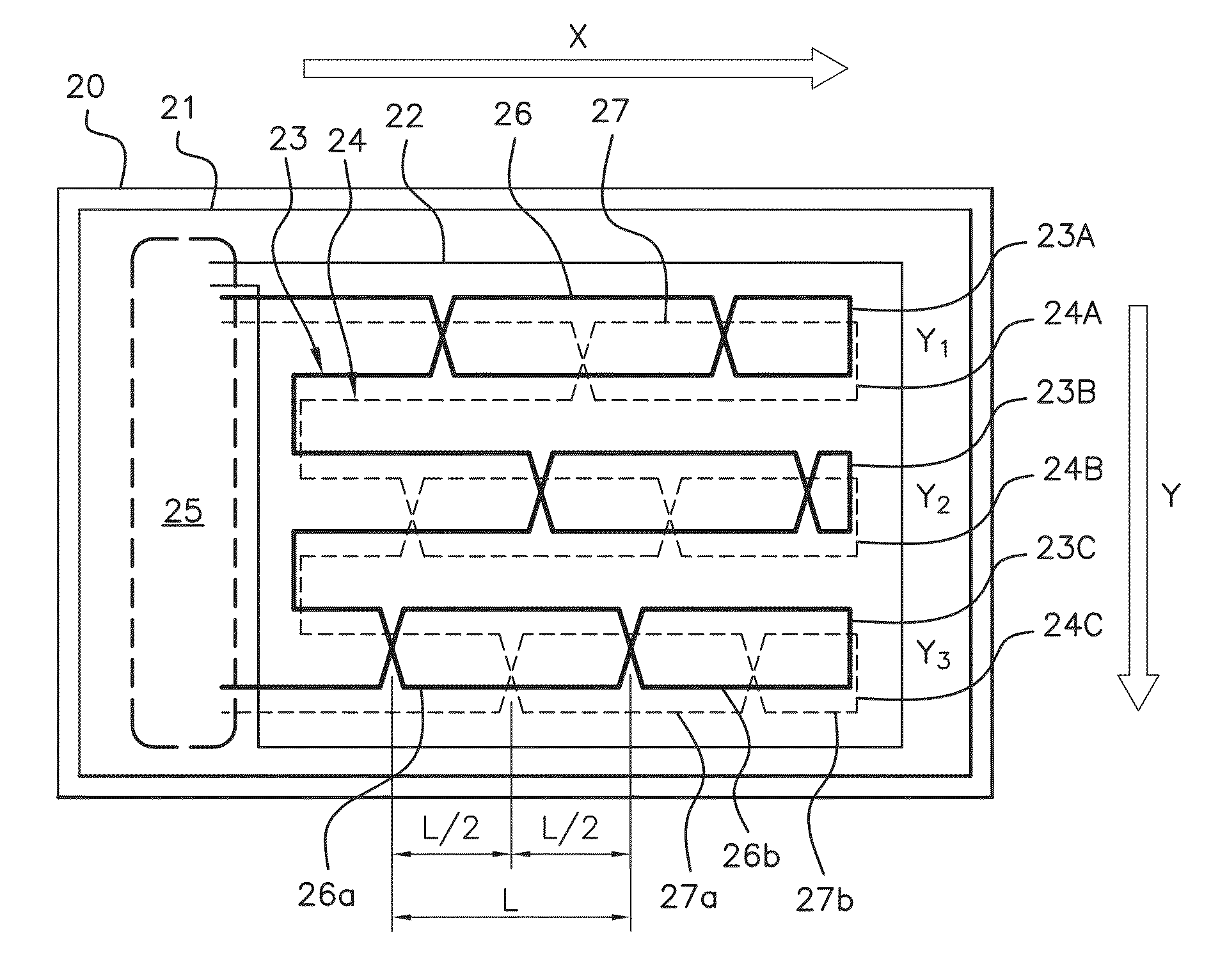
[0027]It should be noted that the figures depict the invention in a detailed manner in order to implement the invention, and said figures can, of course, be used to better define the invention where necessary.

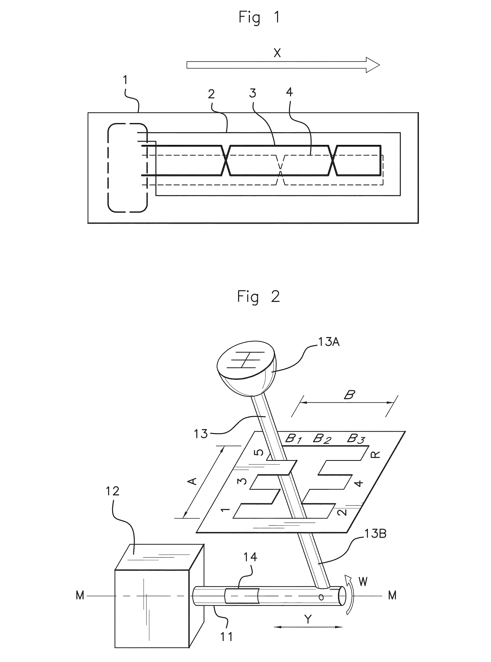
[0028]The sensor according to the invention is intended in particular to be mounted in a vehicle, in particular an automotive vehicle, directly above a drive shaft, in order to determine the position thereof with the help of a target mounted on said shaft. This target may be present in a manner known per se in the form of a plaque made from a conductive material permitting the circulation of eddy currents.

[0029]Consequently, with reference to FIG. 2, the invention will be presented in the case of an automotive vehicle comprising a shaft 11 of a manual gearbox 12 operated by a gearshift lever 13. This example is not a limiting factor for the invention, which applies to any type of vehicle and more broadly to any type of drive shaft, of which it is wished to determine the positio...


PUM


Abstract

An inductive sensor for measuring the position of a shaft of a vehicle in a first direction (X) and a second direction (Y), from a target mounted on the shaft. The sensor (20) includes a printed circuit board (21) including at least one first receiving coil (23), at least one second receiving coil (24) and at least one transmitting coil (22) surrounding the first receiving coil and the second receiving coil. The first receiving coil and the second receiving coil each include a plurality of N portions (23A, 23B, 23C, 24A, 24B, 24C) that are electrically connected to one another and are disposed side by side on the printed circuit in the second direction, each portion extending on the printed circuit in the first direction in such a way as to determine the position of the target both in the first direction and in the second direction.

Description

FIELD OF THE INVENTION[0001]The present invention relates to the field of measurement sensors, in particular for an automotive vehicle, and relates more particularly to a sensor for measuring the position of a drive shaft in two spatial directions, as well as to an automotive vehicle comprising such a sensor.BACKGROUND OF THE INVENTION[0002]In an automotive vehicle, it is known to utilize a gearshift lever or an electrical control in order to select a ratio or a function of a gearbox (forward, rear, neutral, parking brake . . . ). This gearshift lever or this electrical control operates a drive shaft connected to the gearbox in order to place it in the position corresponding to the function or to the selected ratio.[0003]It is known to use a sensor for measuring the position of the shaft in order to permit the management of the engine parameters by an electronic control unit of the vehicle. Such a sensor measures the position of the shaft and then transmits this information to the e...

Claims


Application Information

Patent Timeline
IPC IPC(8): G01D5/20
CPCG01D5/2073F16H63/42G01D5/12G01D5/2053
Inventor GERARDIERE, OLIVIERFONTANET, ALAIN
Owner VITESCO TECH GMBH
Why Eureka
Try Eureka