
Backlight unit for holographic display apparatus and holographic display apparatus including the same

a technology of holographic display and backlight unit, which is applied in the direction of holographic process, lighting and heating apparatus, instruments, etc., can solve the problems of limited number of viewpoints that can be displayed, eye fatigue, and the requirement of light modulator having both a very high resolution and a large amount of processed data

Active Publication Date: 2016-05-26
SAMSUNG ELECTRONICS CO LTD
View PDF6 Cites 63 Cited by
  • Summary
  • Abstract
  • Description
  • Claims
  • Application Information

AI Technical Summary

Benefits of technology

The patent describes a backlight unit for a binocular holographic display apparatus that provides hologram images with different viewpoints for two viewing zones. The backlight unit includes a light source unit that provides illumination light, a light guide plate that includes a light incidence surface onto which the illumination light is incident and a light emission surface from which the illumination light is emitted, an input coupler that advances the illumination light into the light guide plate, and an output coupler that emits the illumination light in different directions for the two viewing zones. The light source unit may include a beam deflector that adjusts the incidence angle of the illumination light. The technical effect of the invention is to provide a more immersive and realistic holographic display apparatus with improved viewing angles and reduced latency.

Problems solved by technology

These methods utilize the a binocular parallax of a viewer's two eyes, but are limited in the number of viewpoints that can be displayed.
Also, there is discordance between depths recognized by the brain and by a viewer's eyes, often creating eye fatigue.
However, a spatial light modulator having both a very high resolution and a very large amount of processed data are required to realize a full holographic display method.

Method used


Image

  • Backlight unit for holographic display apparatus and holographic display apparatus including the same
  • Backlight unit for holographic display apparatus and holographic display apparatus including the same
  • Backlight unit for holographic display apparatus and holographic display apparatus including the same

Examples


Embodiment Construction

[0049]Reference will now be made in detail to exemplary embodiments which are illustrated in the accompanying drawings, wherein like reference numerals refer to like elements throughout. In this regard, the present exemplary embodiments may have different forms and should not be construed as being limited to the descriptions set forth herein. Accordingly, the exemplary embodiments are merely described below, by referring to the figures, to explain aspects. As used herein, the term “and / or” includes any and all combinations of one or more of the associated listed items. It will also be understood that when a layer is referred to as being “on” another layer or substrate, it can be directly on the other layer or substrate, or intervening layers may also be present.

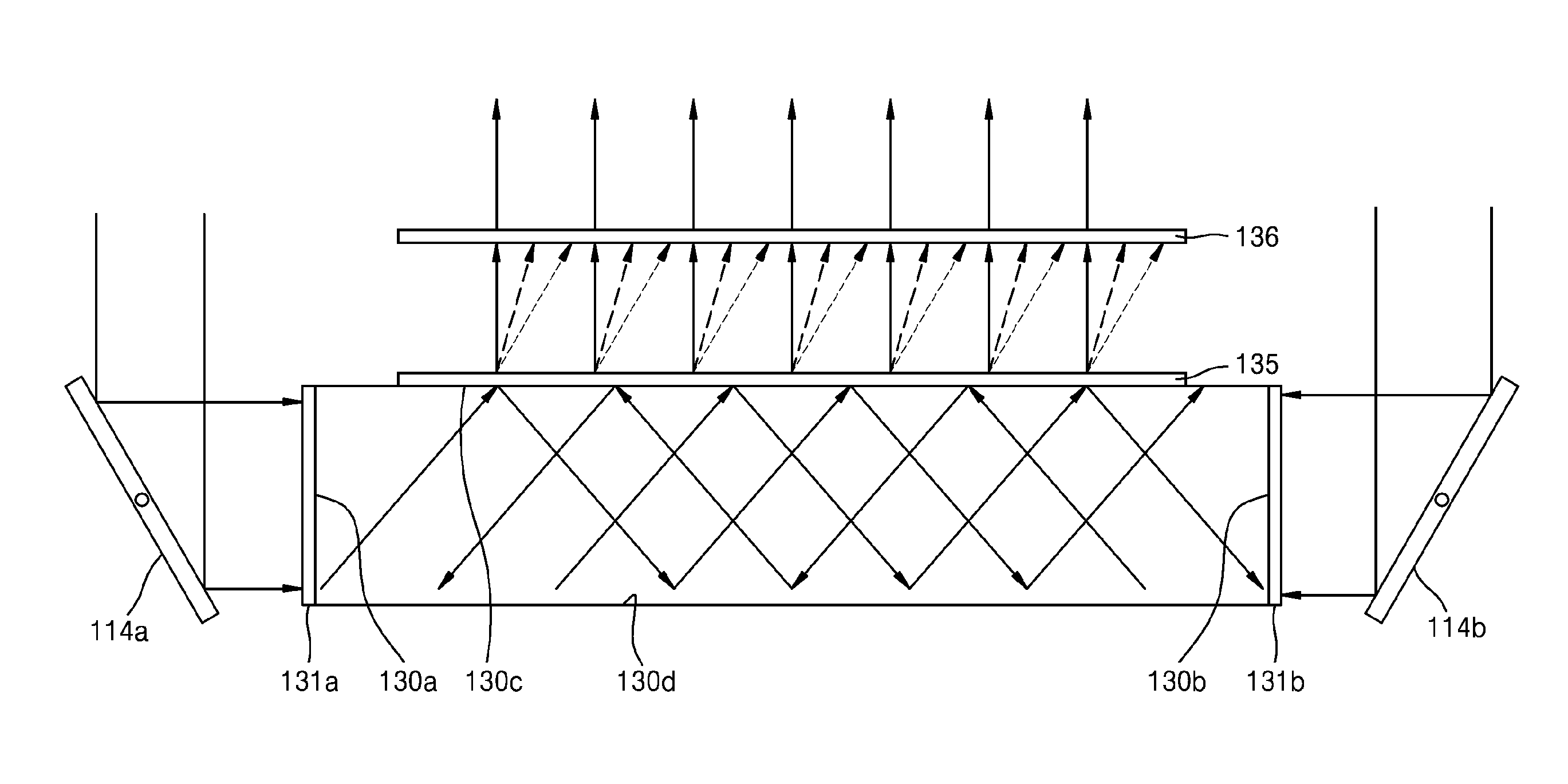
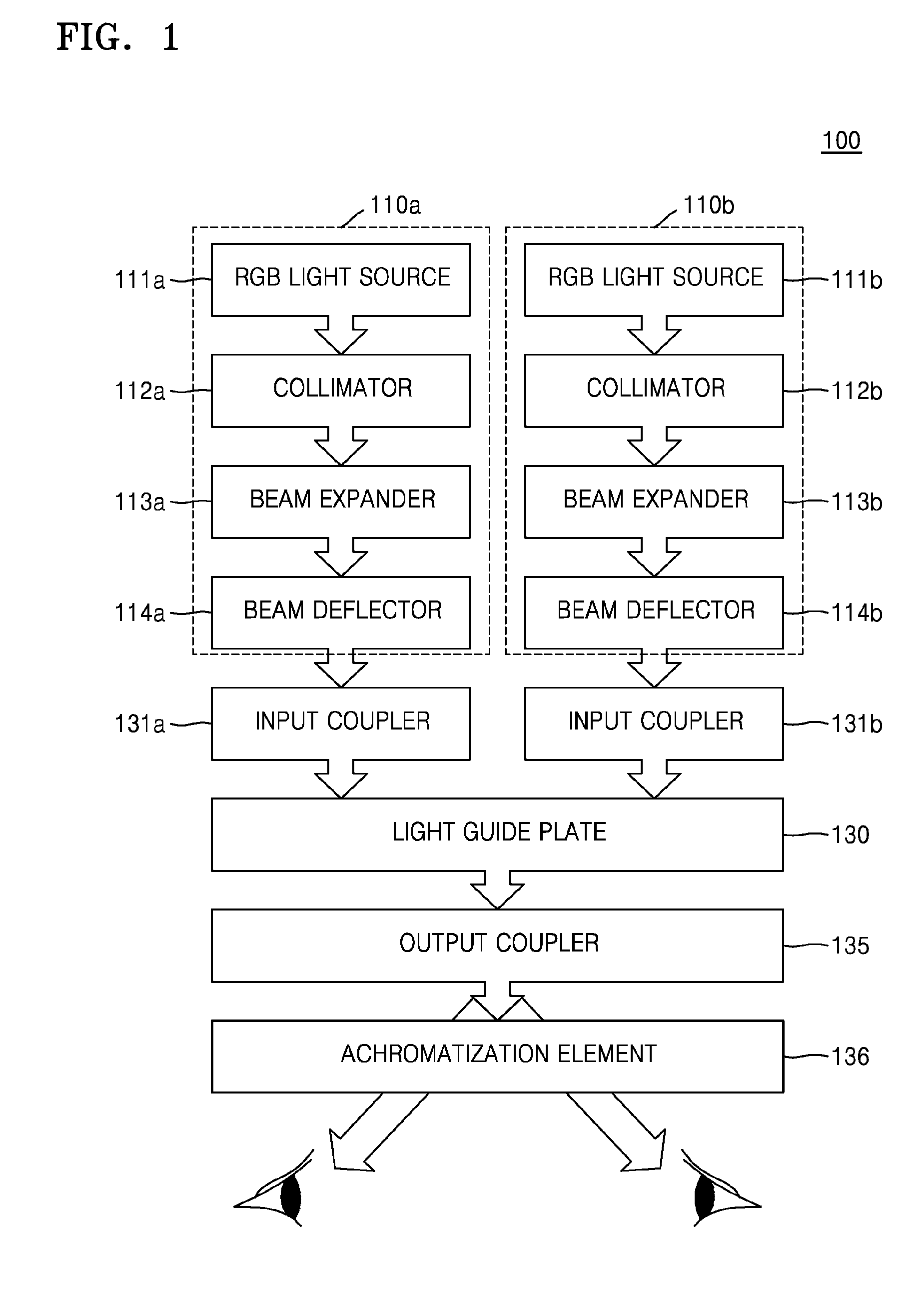
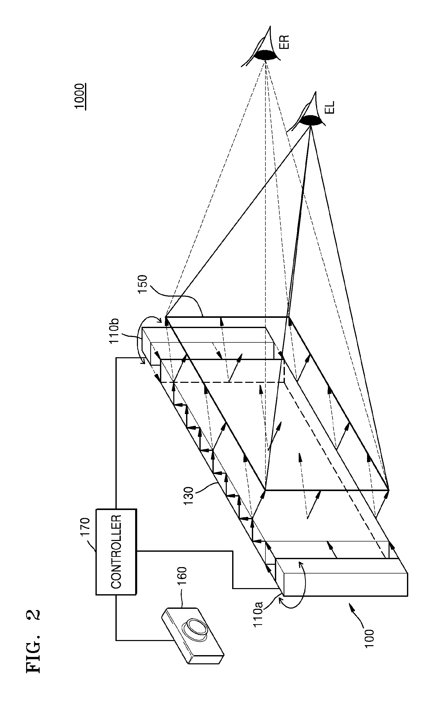
[0050]FIG. 1 is a block diagram illustrating a schematic structure of a backlight unit (BLU) 100 according to an exemplary embodiment. Referring to FIG. 1, the BLU 100 may include light source units 110a and 110b, a light gui...


PUM


Abstract

A backlight unit (BLU), for a binocular holographic display apparatus, and the binocular holographic display apparatus including the BLU are provided. The BLU includes: a light source unit that emits coherent illumination light; and a light guide plate that is transparent and includes a light incidence surface onto which the coherent illumination light emitted by the light source unit is incident and a light emission surface through which the illumination light is output. The light source unit includes a beam deflector that adjusts an incidence angle of the illumination light incident onto the light guide plate.

Description

RELATED APPLICATIONS[0001]This application claims priority from Russian Patent Application No. 2014146782, filed on Nov. 20, 2014, in the Russian Patent Office and Korean Patent Application No. 10-2014-0178716, filed on Dec. 11, 2014, in the Korean Intellectual Property Office, the disclosures of which are incorporated herein in their entireties by reference.BACKGROUND[0002]1. Field[0003]Apparatuses consistent with exemplary embodiments relate to a backlight unit (BLU) and a holographic display apparatus including the same, and more particularly, to a BLU for a binocular holographic display apparatus for providing hologram images having different viewpoints to two viewing zones and a binocular holographic display apparatus including the same.[0004]2. Description of the Related Art[0005]Apparatuses requiring the use of glasses, as well as non-glasses apparatuses have been developed for displaying three-dimensional (3D) images. Method of display requiring glasses include polarization ...

Claims


Application Information

Patent Timeline
Patent Type & Authority Applications(United States)
IPC IPC(8): F21V8/00G03H1/12G02B5/32G02B27/00G02B27/30G02B27/10
CPCG02B6/0023G02B6/0068G02B6/0031G03H1/12G02B27/10G02B5/32G02B27/0093G02B27/30G02B6/005G03H1/2286G03H1/2294G03H2001/2223G03H2001/2242G03H2222/18G03H2222/34G03H2223/16G03H2226/05
Inventor MOROZOV, ALEXANDER V.PUTILIN, ANDREY N.DUBYNIN, SERGEY E.DUBININ, GERMAN B.KOPENKIN, SERGEY S.BORODIN, YURIY P.KIM, SUNILAN, JUNGKWUENCHOI, CHILSUNGLEE, HONGSEOK
Owner SAMSUNG ELECTRONICS CO LTD
Learn More