Touch panel structure
- Summary
- Abstract
- Description
- Claims
- Application Information
AI Technical Summary
Benefits of technology
Problems solved by technology
Method used
Image

Examples
Embodiment Construction
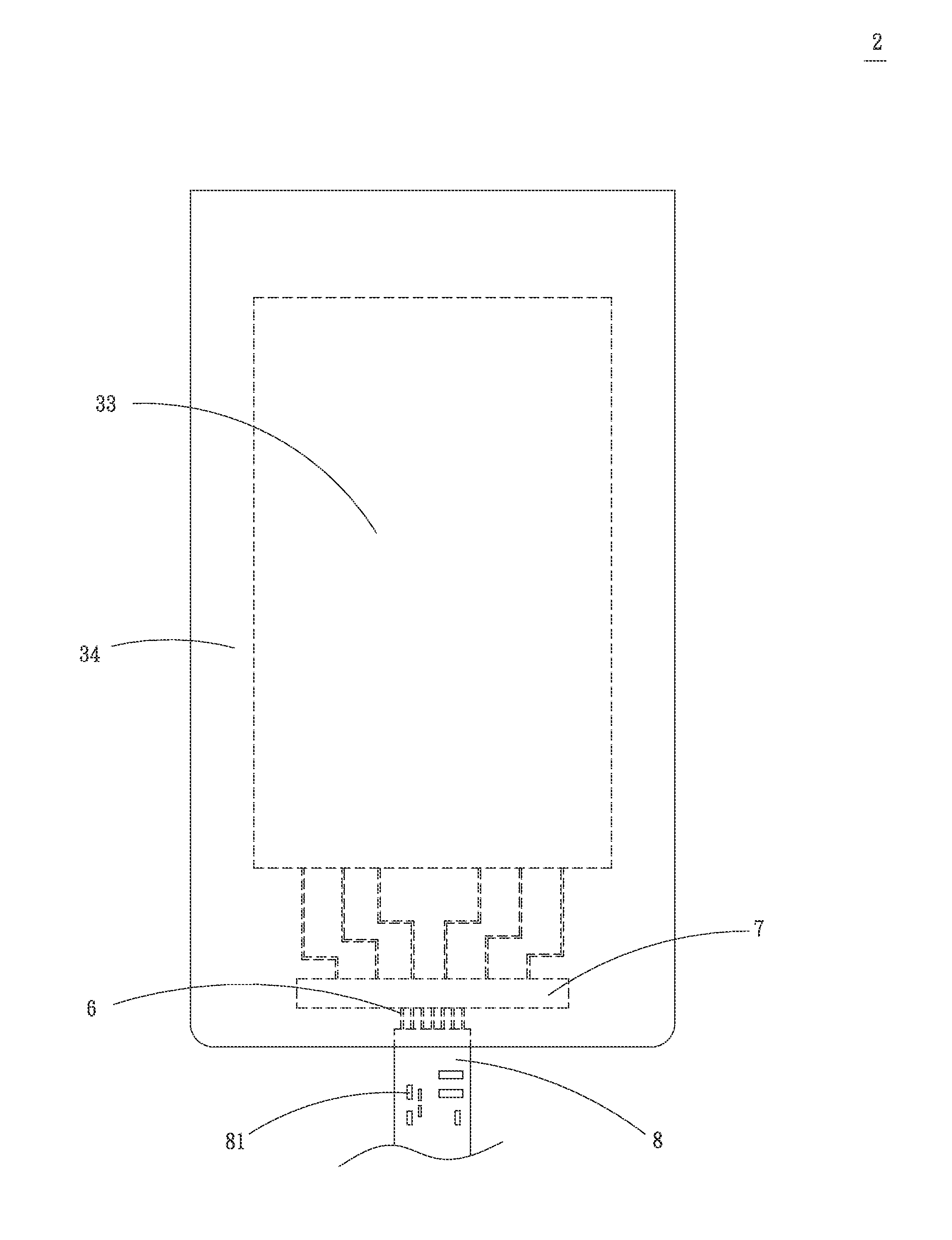
[0015]Please refer to FIGS. 3 and 4. FIG. 3 is a plane view of a preferred embodiment of the touch panel structure of the present invention. FIG. 4 is a sectional view of the preferred embodiment of the touch panel structure of the present invention. According to the preferred embodiment, the touch panel structure 2 of the present invention includes a transparent substrate 3, a shield layer 4, a touch electrode layer 5, a lead layer 6, an integrated circuit 7 and a flexible circuit board 8.
[0016]The transparent substrate 3 has a first face 31 and a second face 32 opposite to the first face 31. The transparent substrate 11 is defined with a touch section 33 at the center of the transparent substrate 11 and a non-touch section 34 around the touch section 33. The material of the transparent substrate 3 is selected from a group consisting of glass, polyethylene terephthalate (PET), polycarbonate (PC), polyethylene (PE), polyvinyl chloride (PVC), polypropylene (PP), polystyrene (PS), pol...
PUM
 Abstract
Description
Claims
Application Information
 - R&D Engineer
- R&D Manager
- IP Professional
- Industry Leading Data Capabilities
- Powerful AI technology
- Patent DNA Extraction
Browse by: Latest US Patents, China's latest patents, Technical Efficacy Thesaurus, Application Domain, Technology Topic.
© 2024 PatSnap. All rights reserved.Legal|Privacy policy|Modern Slavery Act Transparency Statement|Sitemap