Friction stir welding method

a friction stir and welding method technology, applied in welding/soldering/cutting articles, non-electric welding apparatus, manufacturing tools, etc., can solve the problems of failure of joining of hollow members, difficult to use friction stir welding method for joining hollow members, and difficult to be joined together, so as to improve the fluidity of metals, facilitate friction stir, and improve the effect of fluidity

Active Publication Date: 2016-06-02
FURUKAWA SKY ALUMINUM CORP
View PDF8 Cites 6 Cited by
  • Summary
  • Abstract
  • Description
  • Claims
  • Application Information

AI Technical Summary

Benefits of technology

[0018]In the present invention, when the joining portions of the members formed of the specific aluminum materials which are not easily joined together by the friction stir welding method are joined together by the friction stir welding method using the rotary tool having the two shoulder members, the initiation tab member formed of one of 1000 series, 3000 series, 6000 series and 8000 series aluminum alloys according to JIS, whose metals can be easily stirred, is disposed in abutting contact with the end faces of the above-described joining portions of the members on the side of initiation of the welding operation, and the probe of the rotary tool is moved through the initiation tab member into the above-described joining portions. Accordingly, when the friction stir welding operation is started, the metal of the initiation tab member can be easily forced to flow toward the rear side of the rotary tool as seen in the direction of its movement relative to the initiation tab member. Under the state wherein the metal of the initiation tab member is effectively forced to flow toward the rear side of the rotary tool, as described above, the rotary tool is moved into the joining portions of the members formed of the specific aluminum materials which are not easily joined together by the friction stir welding method.
[0019]Subsequently, in the joining portions of the members formed of the specific aluminum materials which are not easily joined together by the friction stir welding method, the metals of those members are friction-stirred by the probe of the rotary tool, and effectively forced to flow toward the rear side of the rotary tool as seen in the direction of its movement relative to the above-described joining portions of the members, whereby the friction stir welding operation can be effectively performed to permit formation of a welded area (joint) on the rear side of the rotary tool without generation of a void which is not sufficiently filled with the metals, and without occurrence of joint defects such as an unwelded part and an insufficiently welded part. Thus, the present invention permits advantageous production of a product having a sound welded area which does not suffer from generation of a hole and occurrence of the joint defects. Further, the present invention permits an effective improvement of fluidity of the metals in the joining portions of the members whose specific aluminum materials are not easily friction-stirred, to advantageously solve a problem of extrusion or discharge of excess metals toward the surfaces of the welded area, and resultant formation of the burr.

Problems solved by technology

Otherwise, the members to be joined together would be deformed by the pressure applied by the rotary tool, giving rise to a problem of failure of joining of those members.
Therefore, it has been difficult to employ the friction stir welding method for joining of hollow members, since it is difficult to dispose the backing plate with respect to the hollow members.
By the way, among aluminum members to be joined together, members formed of a cast aluminum alloy and 2000 series, 4000 series, 5000 series and 7000 series aluminum alloys according to JIS are considered difficult to be joined together by the friction stir welding method, since metals of those members are difficult to be friction-stirred, and are not sufficiently forced to flow by a friction-stirring action.
Therefore, in the case where the above-indicated aluminum members are joined together by the friction stir welding method by using the rotary tool having the two shoulder members, such as the bobbin tool and self-reacting tool described above, the metals of those aluminum members do not sufficiently flow toward the rear side of the rotary tool as seen in the direction in which the welding operation proceeds.
Accordingly, a hole not filled with the metals is generated in the welded area (joint) formed by the above-described welding operation, or the welded area has defects such as an unwelded part or an insufficiently welded part, resulting in failure of formation of a sound welded area.
Further, the welded area formed by the above-described welding operation suffers from considerable formation of burr, resulting in deterioration of the appearance of the welded area, for example.

Method used


Image

  • Friction stir welding method
  • Friction stir welding method
  • Friction stir welding method

Examples


example 1

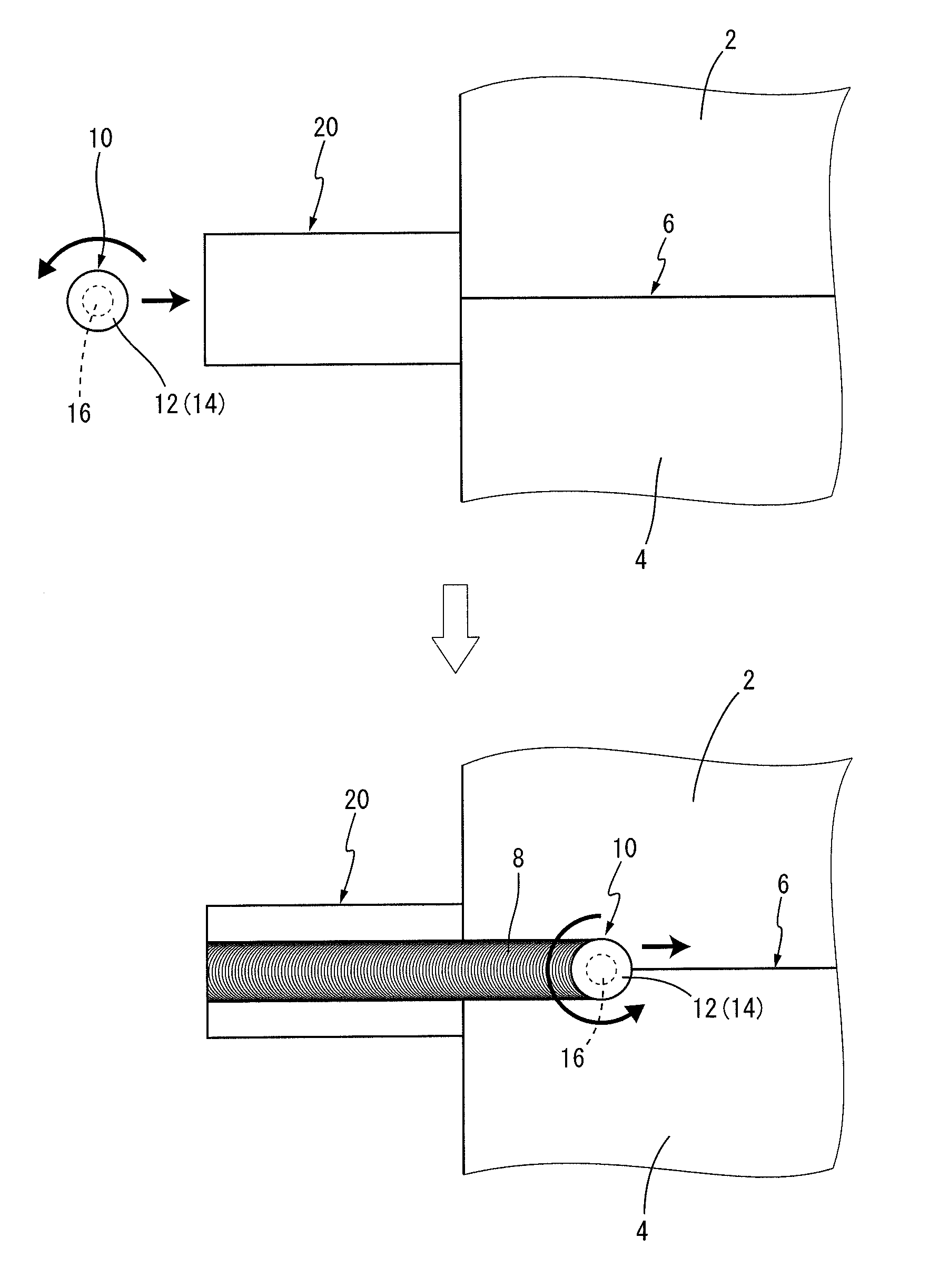
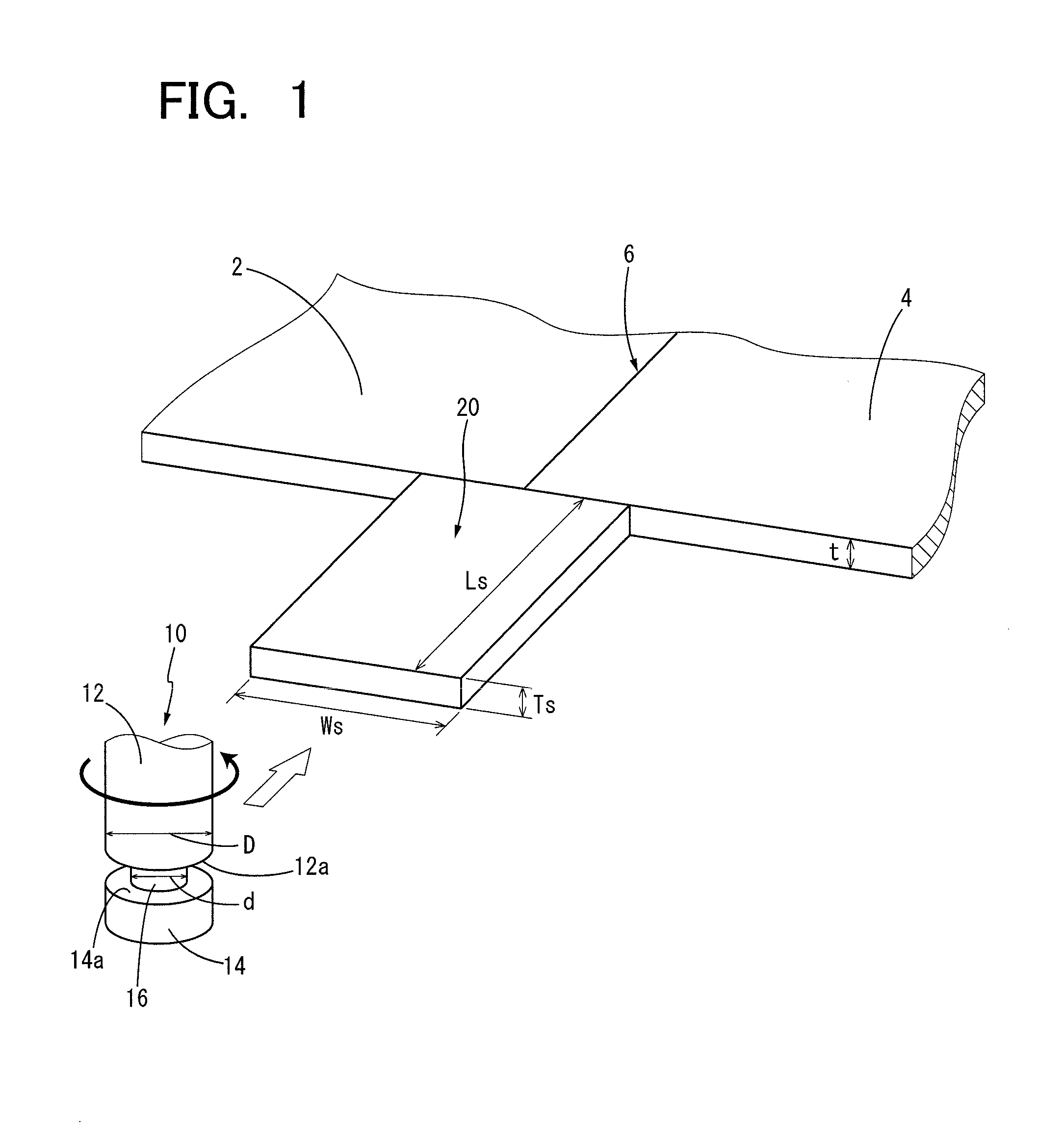
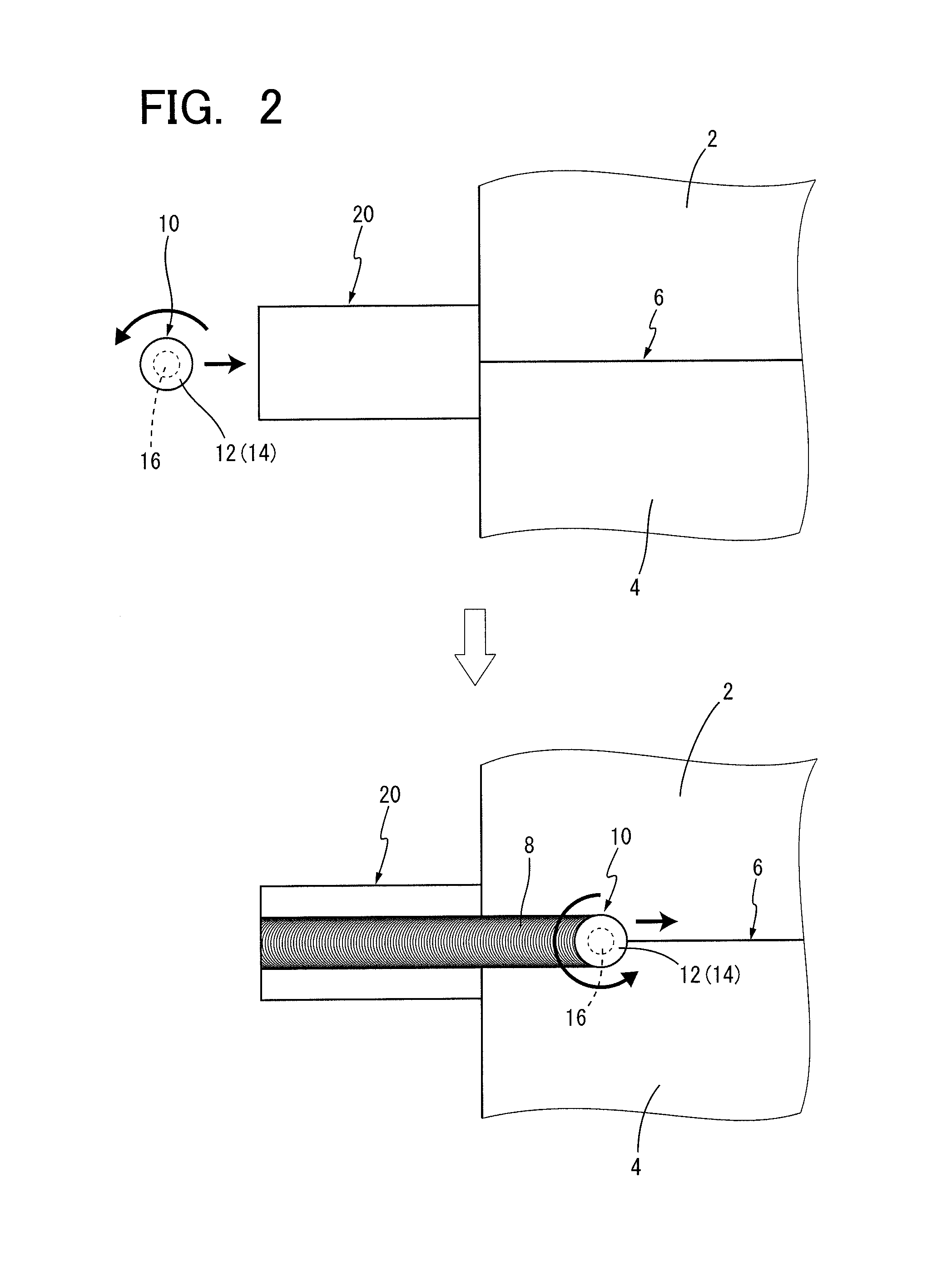
[0048]A planar first member (2) and a planar second member (4) each of which is formed of one of various aluminum materials indicated in Tables 1 and 2 given below, and has a thickness (t) of 2.8-9.2 mm, a width of 300 mm and a length of 5000 mm were butted on each other at their side faces which are opposed to each other in the direction of their width, to provide an abutting part (6). The first and second members (2, 4) were fixed on a table having a gap provided so as to be located below the abutting part (6) of the two members (2, 4). A planar initiation tab member (20) which is formed of one of various aluminum materials indicated in Tables 1 and 2 and has a thickness (Ts), a length (Ls) in a welding direction and a width (Ws) in a direction perpendicular to the welding direction, as indicated in Tables 1 and 2, was held in abutting contact with an end portion of the abutting part (6) of the two members (2, 4) on the side of initiation of a welding operation, as shown in FIG. 1...

example 2

[0053]A first member (2) and a second member (4) each of which is a rolled sheet formed of an aluminum material: 5454-O, and has a thickness (t) of 4.0 mm, a width of 300 mm and a length of 5000 mm were butted on each other in the direction of their width, to provide an abutting part (6). The first and second members (2, 4) were fixed on a table having a gap provided so as to be located below the abutting part (6) of the two members (2, 4). An initiation tab member (20) which is formed of an aluminum material: 1200 and has a thickness (Ts) of 4.0 mm, a length (Ls) in a welding direction and a width (Ws) in a direction perpendicular to the welding direction, as indicated in Table 3 given below, was abutted on an end portion of the abutting part (6) of the two members (2, 4) on the side of initiation of the welding operation, and fixed on the table, like the two members (2, 4).

[0054]A friction stir welding operation was performed as in the Example 1, by using, as a rotary tool, a bobb...

example 3

[0056]A planar termination tab member (22) which is formed of one of various aluminum materials indicated in Tables 4 and 5 given below, and which has a length (Le) in the welding direction, a width (We) in a direction perpendicular to the welding direction and a thickness (Te), as indicated in Tables 4 and 5, was held in abutting contact with end faces of the two planar members (2, 4) in the abutting part (6) on the side of termination of the welding operation. The friction stir welding operation was started as in the FSW Examples 1-20 of the Example 1, and terminated by moving the bobbin tool (10) that had been moved across the abutting part (6) in the longitudinal direction thereof, into the termination tab member (22) from the terminal end of the abutting part (6), and moving the bobbin tool (10) through the termination tab member (22) in the welding direction, as shown in FIG. 4. When the friction stir welding operation was terminated as described above, the bobbin tool (10) wa...


PUM

PropertyMeasurementUnit
diameteraaaaaaaaaa
thicknessaaaaaaaaaa
thicknessaaaaaaaaaa

Abstract

A friction stir welding method which permits advantageous production of a product which has a sound welded area without joint defects, by joining together two members formed of the same material or respective different materials selected from a cast aluminum alloy and 2000 series, 4000 series, 5000 series and 7000 series aluminum alloys which are considered difficult to be joined together by the friction stir welding method. An initiation tab member formed of a 1000 series, 3000 series, 6000 series or 8000 series aluminum alloy is disposed in abutting contact with end faces of joining portions of first and second members (in an abutting part), on the side of initiation of the welding operation, and the friction stir welding operation is performed by moving a probe of a rotary tool through the initiation tab member into the joining portions of the two members.

Description

CROSS REFERENCE TO RELATED APPLICATION[0001]This application is a continuation of the International Application No. PCT / JP2014 / 070732 filed on Aug. 6, 2014, which claims the benefit under 35 U.S.C. §119(a)-(d) of Japanese Application No. 2013-168060 filed on Aug. 13, 2013 and Japanese Application No. 2013-168061 filed on Aug. 13, 2013, the entireties of which are incorporated herein by reference.BACKGROUND OF THE INVENTION[0002]1. Field of the Invention[0003]The present invention relates to a friction stir welding method, and more particularly to a method of advantageously joining together members formed of materials which are considered difficult to be joined together by the friction stir welding method, such as a cast aluminum alloy and 2000 series, 4000 series, 5000 series and 7000 series aluminum alloys, by the friction stir welding method using a rotary tool such as a bobbin tool and a self-reacting tool, which has two shoulder members and which is configured to perform a frict...

Claims


Application Information

Patent Timeline
Patent Type & Authority Applications(United States)
IPC IPC(8): B23K20/12
CPCB23K20/1245B23K20/122B23K20/124B23K20/1255B23K20/129B23K20/2336B23K2101/18B23K2101/28B23K2103/10B23K2103/18
Inventor FUKUDA, TOSHIHIKOMIYAZAKI, SATOSHI
Owner FURUKAWA SKY ALUMINUM CORP
Why Eureka
Try Eureka