Method of Operation of a Gas Turbine Engine

a gas turbine engine and combustor technology, applied in the direction of machines/engines, mechanical equipment, light and heating equipment, etc., can solve the problems of low thermodynamic efficiency, difficult design, and low efficiency at low power, so as to save weight, improve thermal efficiency, and waste heat

Inactive Publication Date: 2016-06-02
ROLLS ROYCE PLC
View PDF15 Cites 13 Cited by
  • Summary
  • Abstract
  • Description
  • Claims
  • Application Information

AI Technical Summary

Benefits of technology

[0010]Accordingly, the present disclosure provides a gas turbine engine which effectively has a variable geometry compressor, turbine and combustor, thereby permitting substantially constant cycle operation. The combustor is capable of varying its capacity without the requirement for valves which operate in high temperature zones, thereby providing good longevity for the valves. Since the airflow through the combustor can be controlled independently of the airflow through the compressor, the air / fuel ratio can easily be maintained. The engine is highly flexible, and can be operated in accordance with different operating methods in order to accommodate differing needs.
[0013]The gas turbine engine may comprise a heat exchanger configured to heat compressor outlet air prior to combustion using heat from turbine outlet air. The heat exchanger may comprise a recuperator or a regenerator. A recuperator has been found to be particularly advantageous in the present arrangement, since variable geometry compressors and turbines may be relatively inefficient when operated at low area positions (i.e. at low power). Consequently, the exhaust gas temperature can be expected to be relatively high, and the compressor exit temperature can be expected to be relatively low. By providing a recuperator, this otherwise wasted heat at low power settings can be recovered, therefore improving thermal efficiency at low power settings.
[0014]The gas turbine engine may comprise a bleed duct in fluid communication with an outlet of the variable geometry engine compressor. The bleed duct may comprise a valve configured to modulate air flow through the bleed duct. Advantageously, the combination of a variable geometry compressor, variable geometry combustor and variable geometry turbine, enables the engine compressor to be utilised to provide a large quantity of bleed air, while satisfying compressor operability requirements. Consequently, a separate load compressor for engine starting and ECS operation may not be required, which thereby saves weight.
[0015]The combustor may comprise a combustor liner and a combustor casing. The bypass control valve may be located in a region of the bypass passage outside of the combustor casing. The combustor may comprise a single combustor can. The gas turbine engine may comprise a scroll located between the combustor outlet and the turbine inlet. Advantageously, the scroll provides a swirl to air entering the turbine inlet, which allows the nozzle guide vane to have a relatively straight aerofoil profile. Consequently, a variable inlet guide can be more readily provided, which may have a relatively small camber.

Problems solved by technology

As a result of the variable cycle, such engines are relatively inefficient at low power, since the resultant relatively low OPR and T4 result in low thermodynamic efficiency.
However, the valves operate in a relatively hot, high pressure area of the gas turbine engine (the combustor can), thereby resulting in a design which is difficult to achieve, in view of difficulties in sealing the valve stems and ensuring adequate life of the components.
Again however, the valves must operate in a high temperature environment, and therefore suffers the same disadvantages of the combustor of U.S. Pat. No. 3,899,886.
Control of constant cycle engines can be difficult, given the large number of control variables and constraints.

Method used


Image

  • Method of Operation of a Gas Turbine Engine
  • Method of Operation of a Gas Turbine Engine
  • Method of Operation of a Gas Turbine Engine

Examples


Embodiment Construction

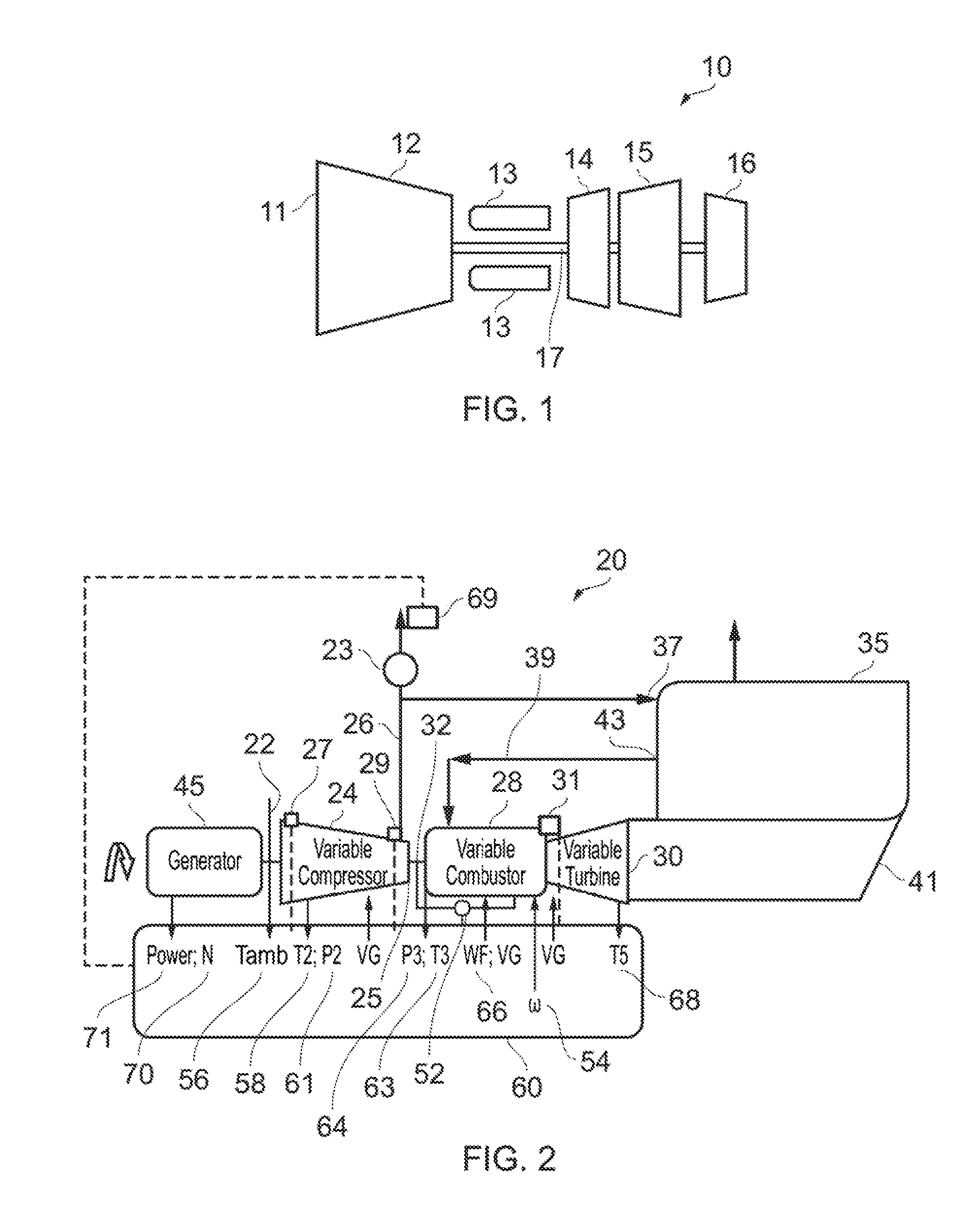
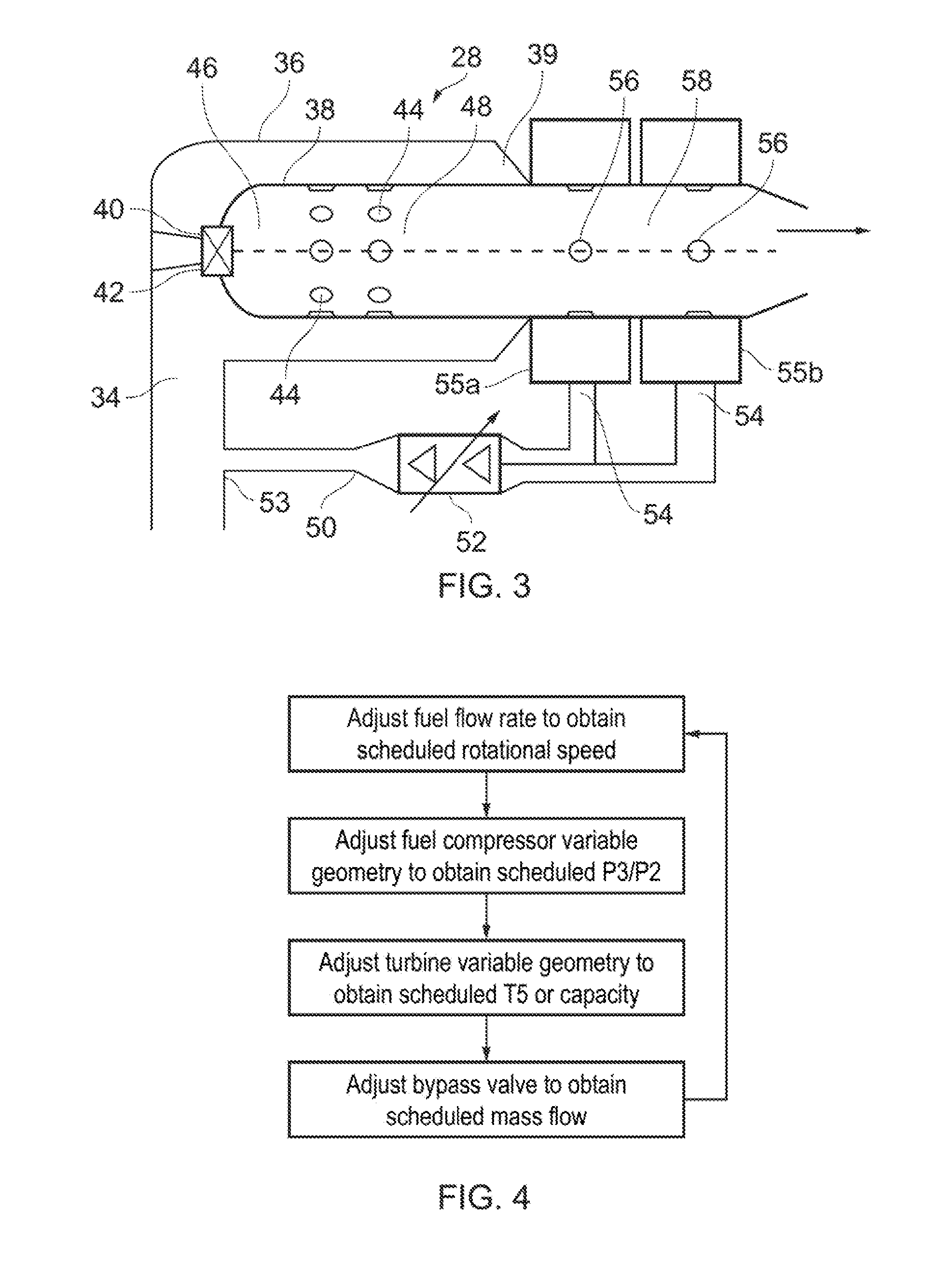
[0031]FIGS. 2 and 3 show a gas turbine engine 20 in accordance with the present disclosure. FIG. 2 shows the components and their interrelationships, and does not necessarily reflect the physical appearance of the engine 20. The engine 20 comprises an inlet 22, which feeds ambient air to a variable geometry compressor 24. An optional compressor bleed 26 is provided downstream of the compressor 24, which takes compressed air from the compressor 24, and delivers this air to an aircraft main engine and / or an aircraft environmental control system for example. The bleed flow is controlled by a bleed valve 23. Downstream of the compressor 24 and bleed 26 is a variable geometry combustor 28 and a bypass passage 50. Respective first and second outlets 34, 53 of the compressor 24 provide air to the combustor 28 and bypass passage 50. In the combustor 28, compressed air from the compressor 24 is mixed with fuel and burnt to produce hot combustion gasses. The hot combustion gasses flow downstr...


PUM


Abstract

A method of operating a gas turbine engine (20) comprising a variable geometry compressor (24), a variable geometry combustor (28), and a variable geometry turbine (30). The method comprises operating the variable geometry combustor (28) such that a corrected flow ωc through a combustion zone (46, 48) of the combustor (28) matches a predetermined value.

Description

FIELD OF THE INVENTION[0001]The present invention relates to a gas turbine engine, a combustor for a gas turbine engine, and methods of operation of a gas turbine engine.BACKGROUND TO THE INVENTION[0002]FIG. 1 shows a gas turbine engine 10 for use as an APU for an aircraft (not shown). The engine 10 comprises, in axial flow series, an air intake duct 11, a gas turbine compressor 12, a combustor 13, a high pressure turbine 14, a low pressure turbine 15, and a load compressor 16. The compressors 12, 16 and turbines 14, 15 are coupled by a shaft 17, and all rotate about the major axis of the gas turbine engine 10 and so define the axial direction of the gas turbine engine 10. Air is fed from the air intake duct 11 to the compressors 12, 16. Compressed air from the gas turbine compressor 12 is fed to the combustor 13, where it is mixed with fuel and burnt. The hot combustion gasses flow through and drive the turbines 14, 15, which in turn drive the compressors 12, 16. Compressed air fro...

Claims


Application Information

Patent Timeline
Patent Type & Authority Applications(United States)
IPC IPC(8): F02C9/32F02C9/54F02C9/18F02C3/13F02C7/22
CPCF02C9/32F02C3/13F02C7/222F05D2240/35F02C9/54F05D2220/32F02C9/18F02C3/14F23R3/26F05D2270/112F05D2270/3061F05D2270/31F02C9/50F02C9/52
Inventor FLETCHER, PAULHILLEL, MALCOLM LAURENCEWALSH, PHILIP PATRICK
Owner ROLLS ROYCE PLC
Why Eureka
Try Eureka