Bearing nut for measuring the rotational speed of a shaft connected to a turbomachine and associated measuring device

a technology of rotating shaft and measuring device, which is applied in the direction of mechanical equipment, manufacturing tools, instruments, etc., can solve the problem of less representative testing of actual operating conditions

Active Publication Date: 2016-06-02
SN DETUDE & DE CONSTR DE MOTEURS DAVIATION S N E C M A
View PDF3 Cites 5 Cited by
  • Summary
  • Abstract
  • Description
  • Claims
  • Application Information

AI Technical Summary

Problems solved by technology

The problem with this technology is that it is necessary to provide a specific part that is equipped with this ring of teeth to be indexed with the engine for each speed measurement.
Firstly, it is not always obvious t

Method used


Image

  • Bearing nut for measuring the rotational speed of a shaft connected to a turbomachine and associated measuring device
  • Bearing nut for measuring the rotational speed of a shaft connected to a turbomachine and associated measuring device
  • Bearing nut for measuring the rotational speed of a shaft connected to a turbomachine and associated measuring device

Examples


Embodiment Construction

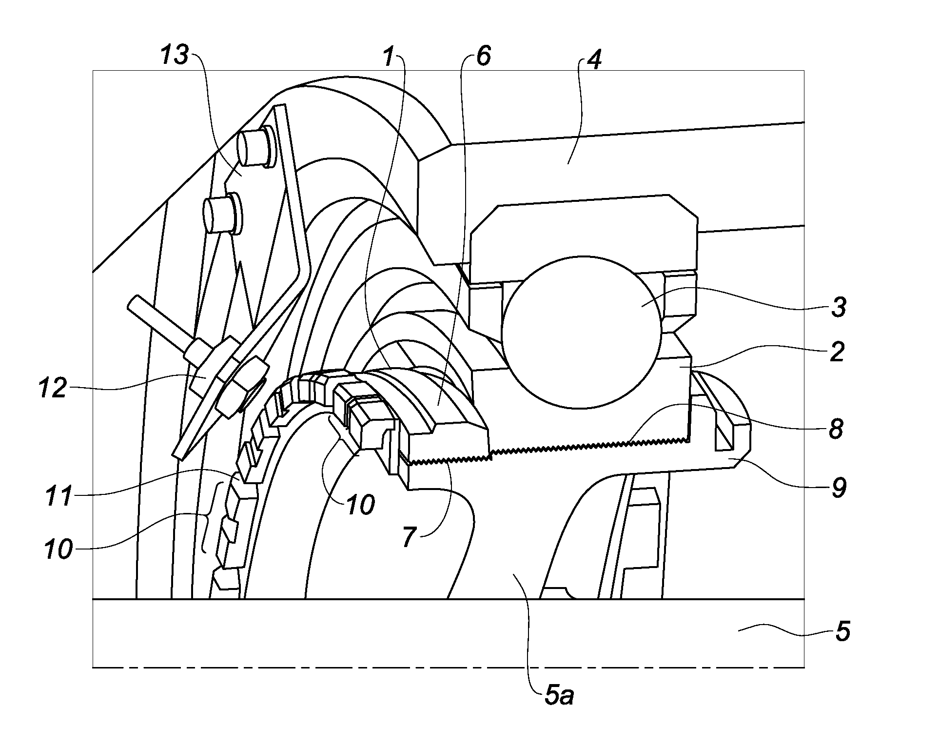
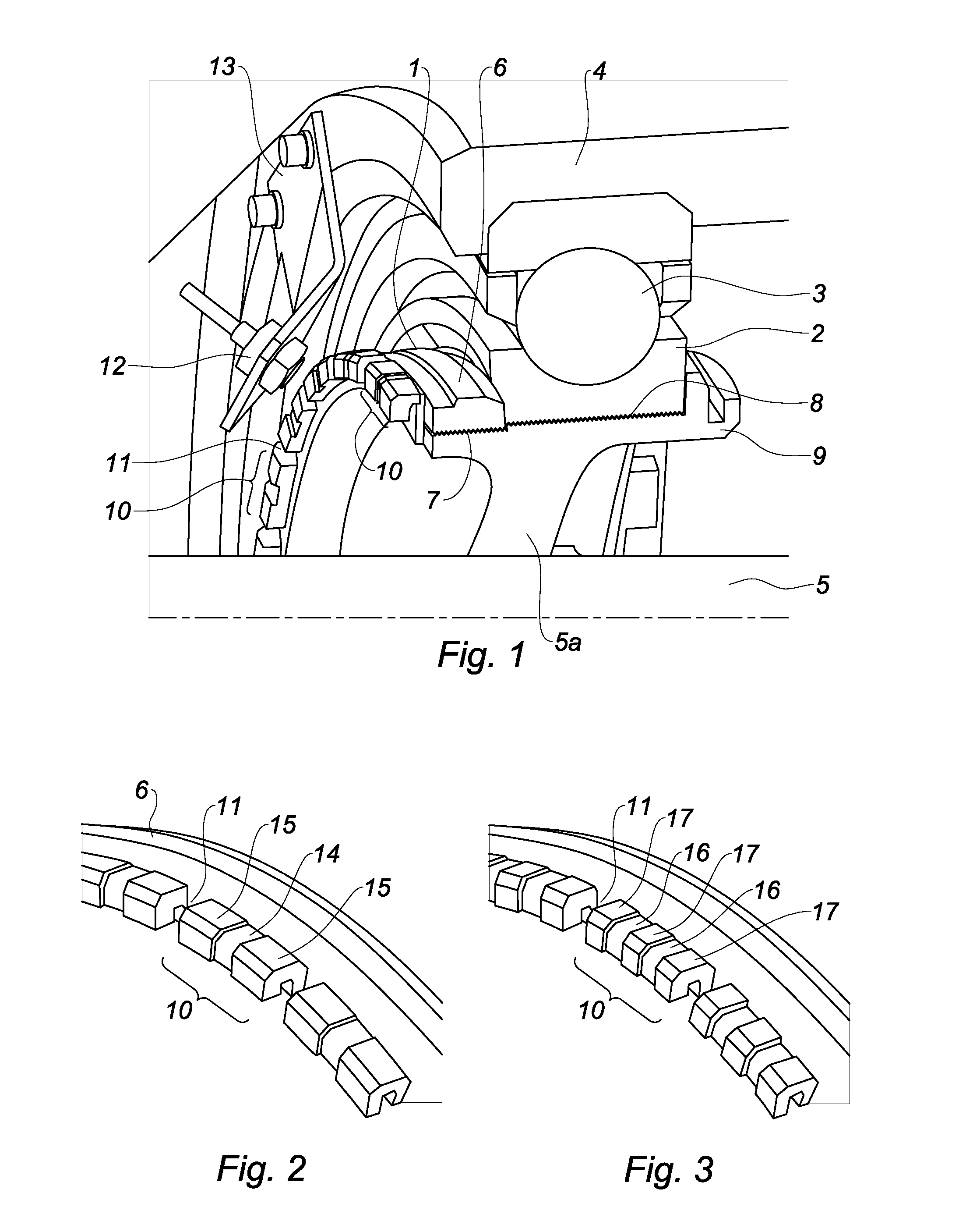
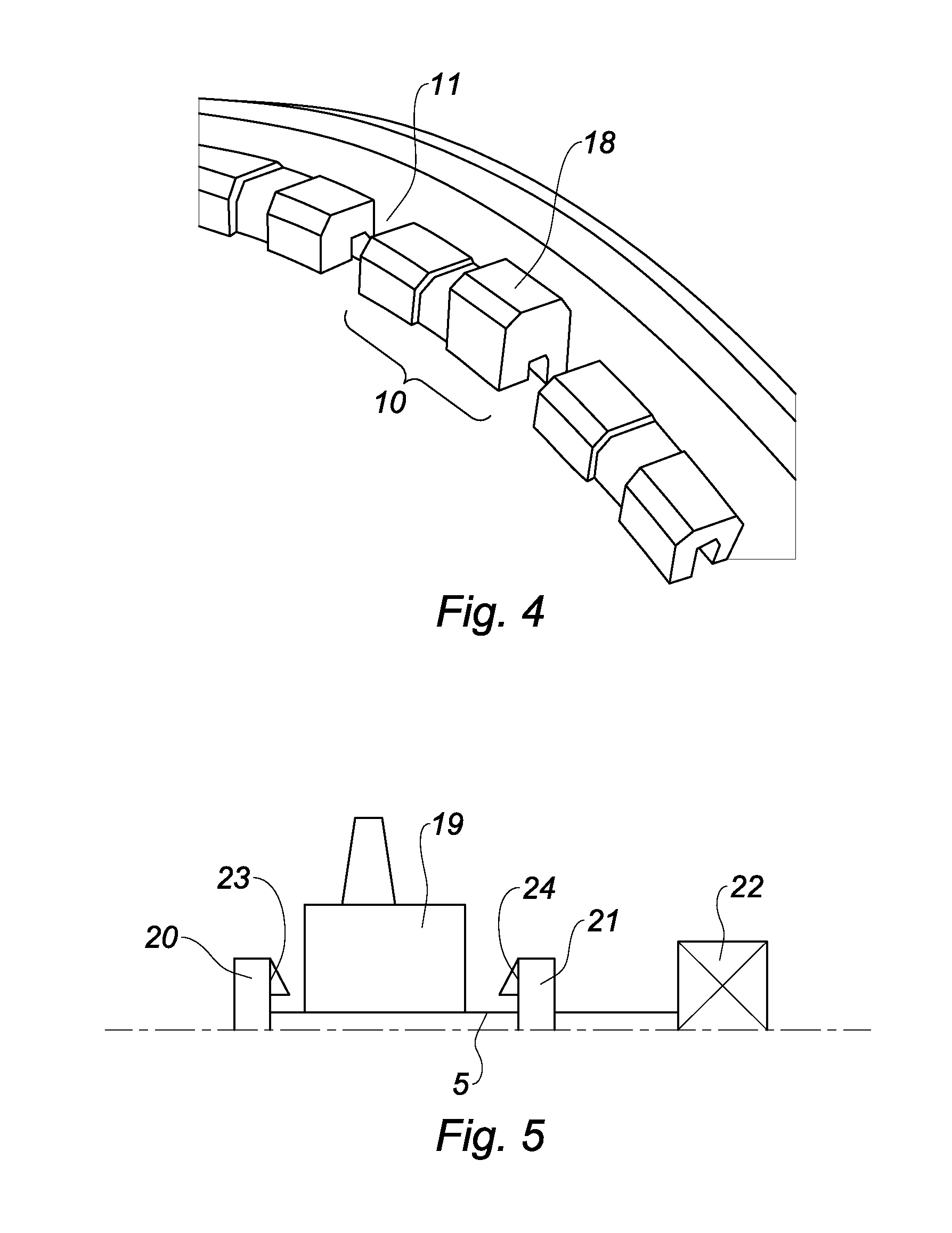
[0007]The invention relates to a nut which has a specified axis and is intended to be screwed around a rotating shaft in order to rigidly connect a part to said shaft, and to interact with a stationary sensor which senses an amount of material in a specified space in order to measure the rotational speed of the shaft, comprising a ring of teeth which are separated by slots and arranged so as to engage with a clamping tool inserted into at least one slot, said nut being characterised in that at least some of the teeth comprise at least one recess which maintains the function of clamping the ring of teeth, said recesses forming, together with the slots separating the teeth, just as many intervals having less material that are intended to be detected by said sensor when passing through the detection space thereof when the nut rotates.

[0008]In this manner, the non-recessed segments on the clamping teeth form a ring of patterns which lead to variations in material density when passing th...


PUM


Abstract

The invention concerns a nut (1) intended to be screwed around a rotating shaft (5) with a view to securing a part (2) to said shaft and to cooperate with a fixed sensor (12) sensing a quantity of material in a pre-defined volume in order to measure the speed of rotation of the shaft, comprising a ring of teeth (10) separated by slots (11), said nut being characterised in that at least a portion of the teeth (10) comprises at least one recess (14, 16) maintaining the clamping function of the ring of teeth, said recesses forming, with the notches separating the teeth, respective material deficit intervals intended to be detected by said sensor when passing through the detection volume of same during the rotation of the nut. It also concerns the use of this nut with a sensor in a rotational speed measuring device and the production of same.

Description

TECHNICAL FIELD[0001]The present invention relates to measuring the rotational speed of a rotating shaft in a turbine engine. The invention more particularly relates to a device for measuring markers, which are rigidly connected to the shaft, as they pass in front of a sensor.PRIOR ART[0002]Accurately measuring the rotational speed of the rotor of a turbine engine is extremely important in order to check the proper functioning thereof.[0003]More particularly, in some apparatuses for testing for blade loss, it is necessary to determine the torque passing through the drive shaft of the rotor. This torque is determined by two measurements of the rotational speed of the shaft, on either side of the rotor during tests. Since the torque is derived from the phase difference between these two measurements, the measurements have to be taken with great accuracy.[0004]It is known to carry out this type of measurement by counting marks, distributed on a circle rotating together with the shaft, ...

Claims


Application Information

Patent Timeline
IPC IPC(8): G01L3/10F16C41/00G01P3/44G01P3/483
CPCG01L3/10G01P3/443F16C41/007G01P3/483G01P3/488G01L3/106F16C2360/00
Inventor ROUSSELIN, STEPHANEADNOT, JEAN-FRANCOISMASCRIER, BENOIT
Owner SN DETUDE & DE CONSTR DE MOTEURS DAVIATION S N E C M A
Why Eureka
Try Eureka