Active quasi circulator

a quasi-circulator and active technology, applied in the field of radio frequency (rf) circuits, can solve the problem that passive devices usually exhibit undesired transmission losses

Active Publication Date: 2016-06-02
INFINEON TECH AG
View PDF1 Cites 4 Cited by
  • Summary
  • Abstract
  • Description
  • Claims
  • Application Information

AI Technical Summary

Problems solved by technology

Moreover, such passive devices usually exhibit undesired transmission losses.

Method used


Image

  • Active quasi circulator
  • Active quasi circulator
  • Active quasi circulator

Examples


Embodiment Construction

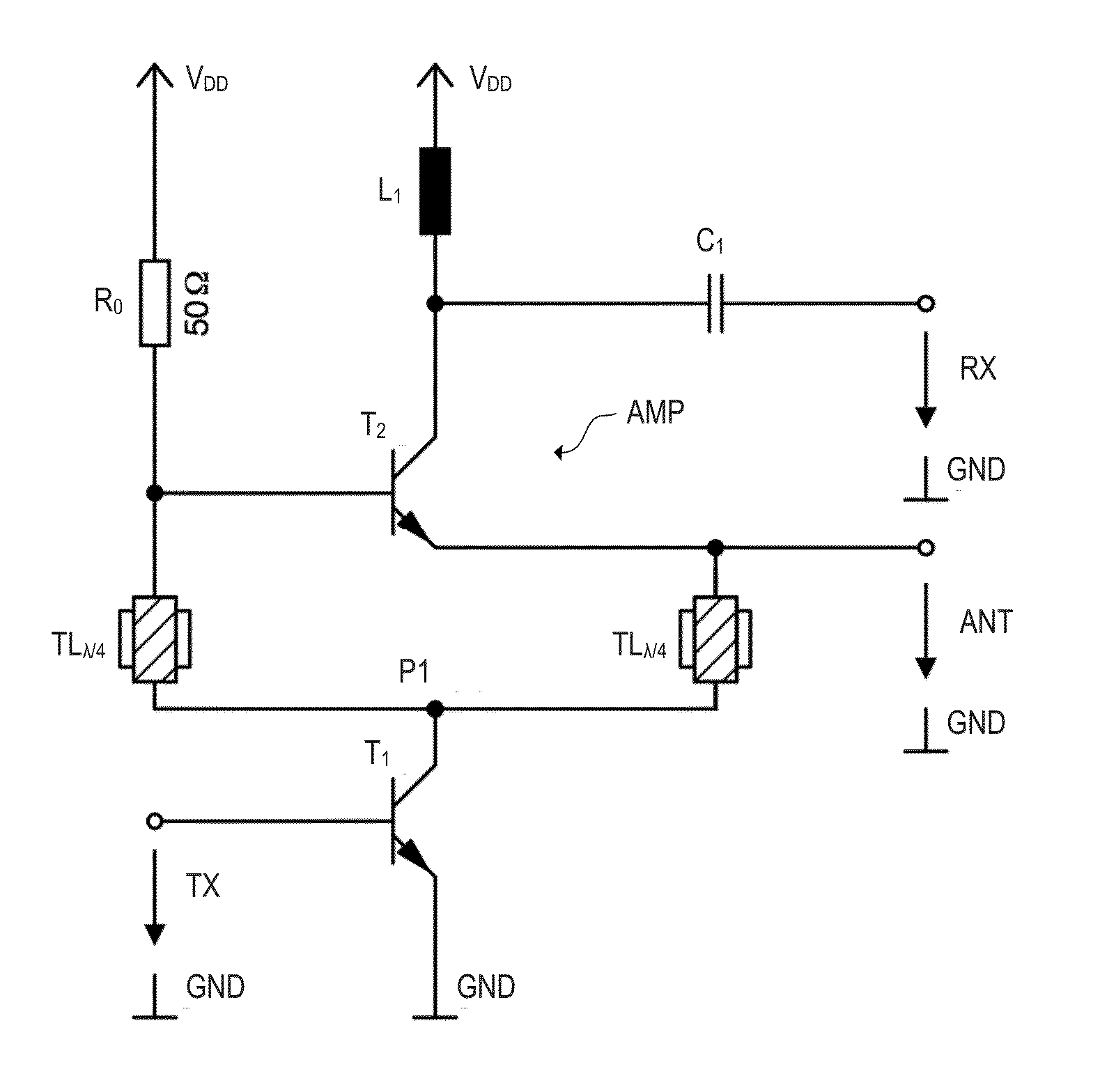
[0018]As mentioned above, a typical function of transmit and receive modules (RF front-ends) with one or more shared transmit and receive antenna is the separation of the strong transmit signal from the weak receive signal. For this purpose, passive devices (e.g., circulators and directional couplers) are commonly used. However, such passive devices often require much space and exhibit undesired transmission losses. One approach to improve the situation is to replace the mentioned passive devices by active devices, which may be designed to be more efficient with regard to losses and smaller in size. Generally, the isolation between an RX port and an TX port of the device is a relevant parameter as it determines the level of the blocker signal (i.e. the portion of the transmit signal which is transmitted from the TX port to the RX port, in an ideal case the blocker signal is zero) of the first devices in the receiver part.

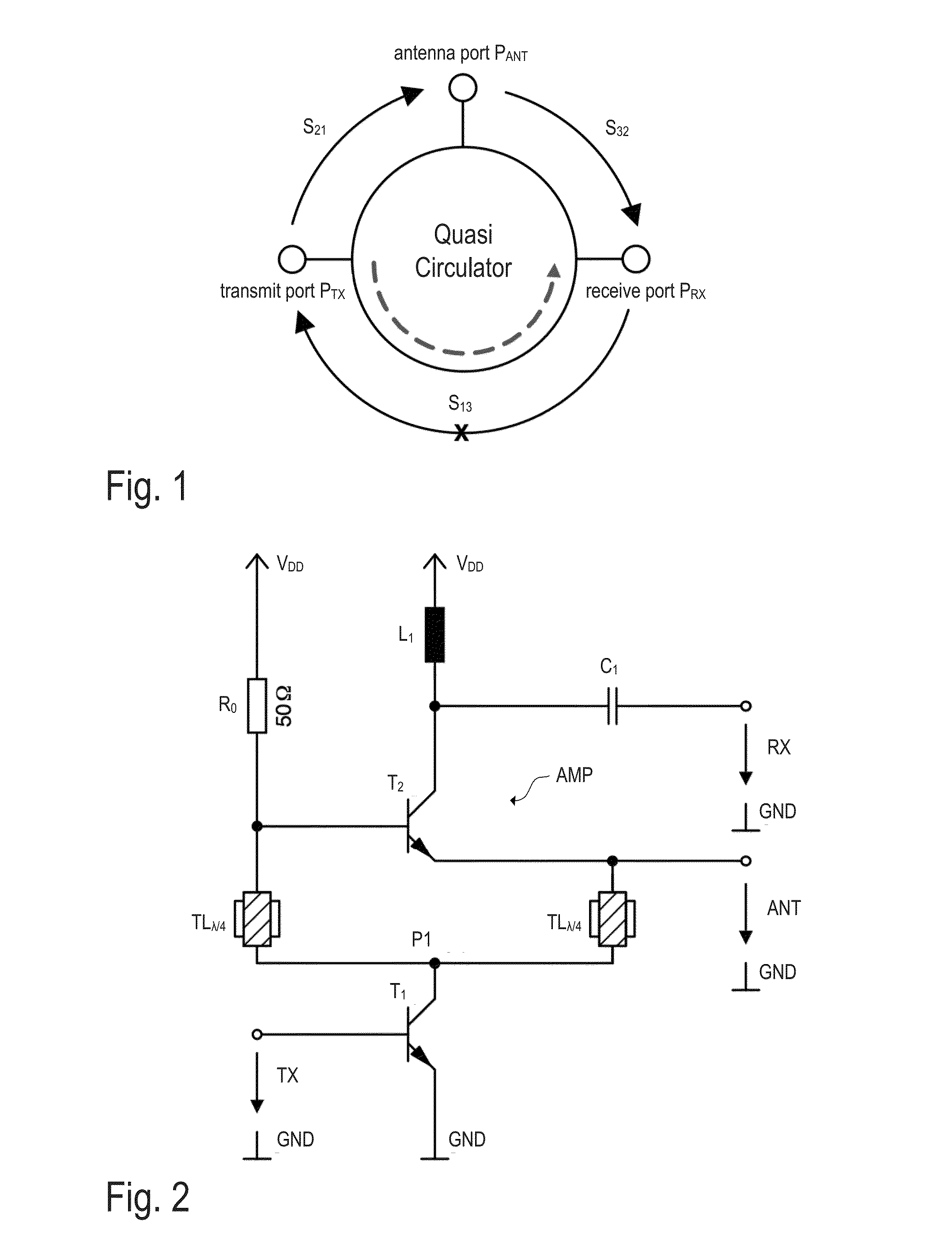
[0019]FIG. 1 illustrates an example circulator in a schematic ...


PUM


Abstract

An RF quasi circulator circuit is described herein. In accordance with one example of the disclosure the circuit includes a receive port, a transmit port and an antenna port as well as a differential amplifier stage having a first input, a second input and an output that is coupled to the receive port. The circuit further includes a first phase shifting element and a second phase shifting element. The first phase shifting element is coupled between the transmit port and the first input of the differential amplifier and the second phase shifting element is coupled between the transmit port and the second input of the differential amplifier. A tunable impedance is coupled to the differential amplifier, and the antenna port is coupled to the first input of the differential amplifier. The tunable impedance is controlled to tune the damping in a signal path from the transmit port to the receive port.

Description

FIELD[0001]The present disclosure relates to the field of radio frequency (RF) circuits, in particular to the field of active circulator and directional coupler circuits.BACKGROUND[0002]Radio frequency (RF) receivers and transceivers can be found in numerous applications, particularly in the field of wireless communications and radar sensors. For example in the automotive sector, there is an increasing demand for radar sensors used in so-called “adaptive cruise control” (ACC) or “radar cruise control” systems. Such systems may be used to automatically adjust the speed of an automobile so as to maintain a safe distance from other automobiles ahead.[0003]Modern radar systems make use of highly integrated RF circuits (MMICs, monolithic microwave integrated circuits), which may incorporate all core functions of an RF transmit and receive module (also referred to as “RF font-end”) of a radar transceiver in one single package (single chip transceiver). Such RF front-ends may include, inte...

Claims


Application Information

Patent Timeline
Patent Type & Authority Applications(United States)
IPC IPC(8): H03H11/38H03F3/45
CPCH01P1/383H01P1/18H03F2203/45034H03F2200/451H03F3/45076H03F1/565H03F3/4508H03F3/60H03H11/34H03H11/36
Inventor WAGNER, CHRISTOPHPORRANZL, MATTHIAS
Owner INFINEON TECH AG
Why Eureka
Try Eureka