
Stereophonic focused hearing

a technology of focused hearing and stereophonics, applied in the field of hearing aid systems, can solve the problems of small area of sound energy intercepted, large effort expended on the part of small microphones, and inability to detect large volumes, etc., and achieve the effect of improving hearing

Active Publication Date: 2016-06-02
ACOUSTIC VISION
View PDF20 Cites 16 Cited by
  • Summary
  • Abstract
  • Description
  • Claims
  • Application Information

AI Technical Summary

Benefits of technology

The patent is about a device and method that improves hearing by using eyewear with sound detectors. The detector on each lens can pick up different sounds at different times, and a processing unit on the eyewear uses software to determine the difference in time between the two detections. This information is used to modify the sound signals sent to a hearing aid device, which then delivers the modified signals to the wearer's ears. This technology can enhance sound quality and make it easier for people to hear what they need to hear more clearly.

Problems solved by technology

Due to problems associated with hearing aid size and weight, and for cosmetic reasons, much effort has been expended to decrease the size of these microphones.
Thus, the area of sound energy intercepted is small and the small microphone is necessarily very sensitive.
The smaller size has worsened problems associated with reception of confusing, unwanted sounds surrounding the listener.
The overall hearing aid performance is often further limited by the proximity of the speaker (in the listener's ear) to the microphone of the hearing aid.
This gives rise to disruptive feedback such as oscillation or whistling.

Method used


Image

  • Stereophonic focused hearing
  • Stereophonic focused hearing
  • Stereophonic focused hearing

Examples


example 1

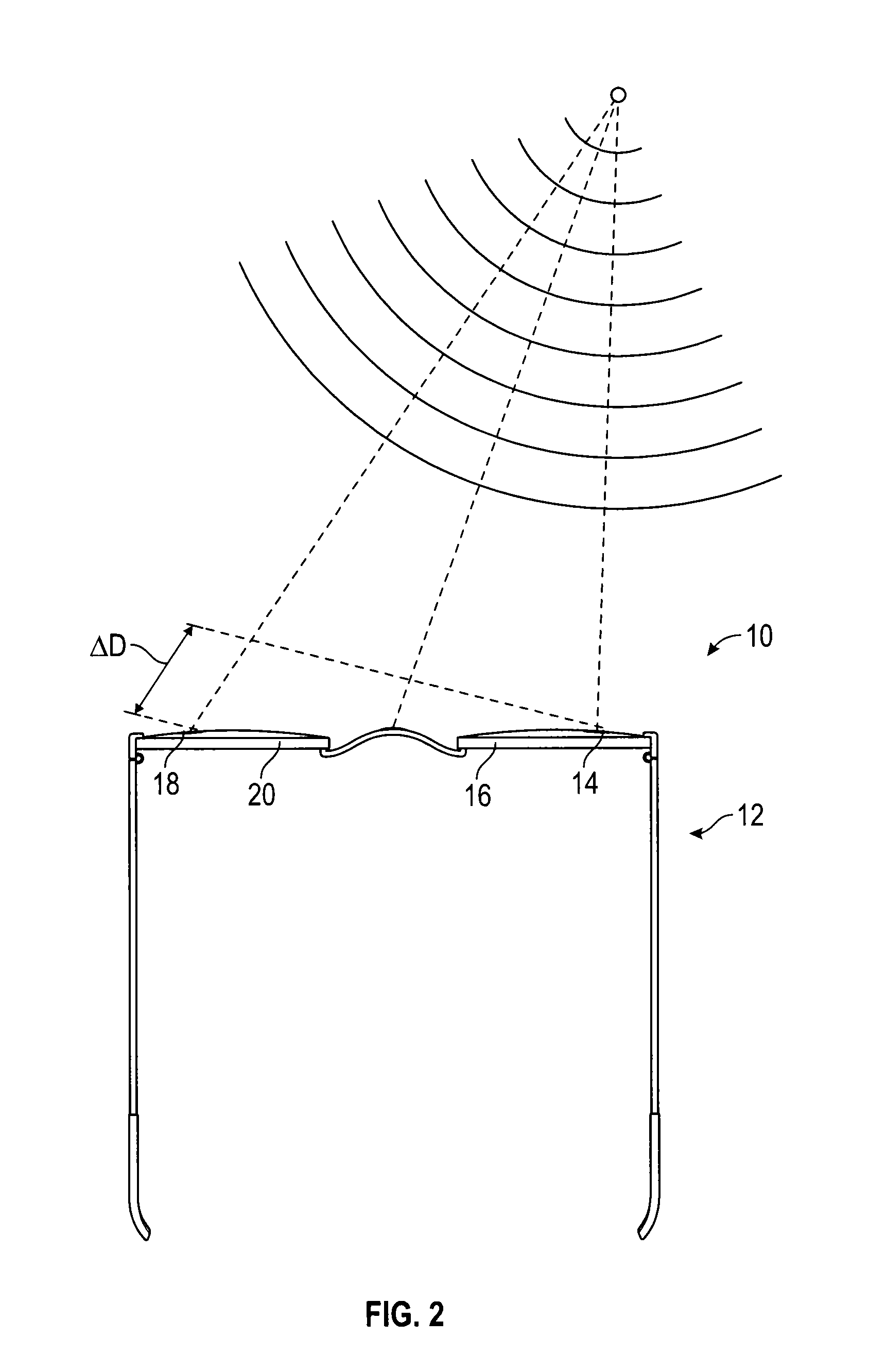
[0040]A signal processor is programmed to enhance the hearing experience of the user by using the following signal characteristics. The first characteristics of the acoustic sound signal is its velocity in air which is about 1100 ft. / s. Assuming a 0° reference to be directly in front of the wearer, the wearer's looking direction, and considering a signal whose origin is N degrees to the right of the wearer, the resulting detection of the assumed signal would happen at the two lenses spaced apart in time because the signal path to the right lens would be shorter than the left lens signal path. This difference, when presented to the human hearing system, gives the wearer the angular deviation from straight-ahead. In a signal processor the signal from N degrees to the right can be identified since it is the same in each lens only displaced in time of arrival, and the angular displacement from 0° of the signal source can be calculated.

[0041]The processor uses triangulation methods known...

example 2

[0042]A further triangulation method allows depth perception of sounds. The distance measurement is based on utilizing two sound transducers at each eyewear lens and using a time of arrival difference measurement to solve two resulting triangles, one for each side of the eyewear. The solution of two oblique triangles is possible because the length of one side of the triangle is known, i.e., the distance between the transducers. The difference in length of the two remaining sides is determined by measuring the slight difference in time of arrival of two identical syllables at the two transduces for each side. Using the above triangle definition, the processor will find the resulting triangle and determine the angle from forward of the origin of that syllable. The distance from the viewer will then calculated by the solution of a third triangle formed by the lines extending from the center of each lens, right and left, at their respective angles from forward. The solution of this thir...


PUM


Abstract

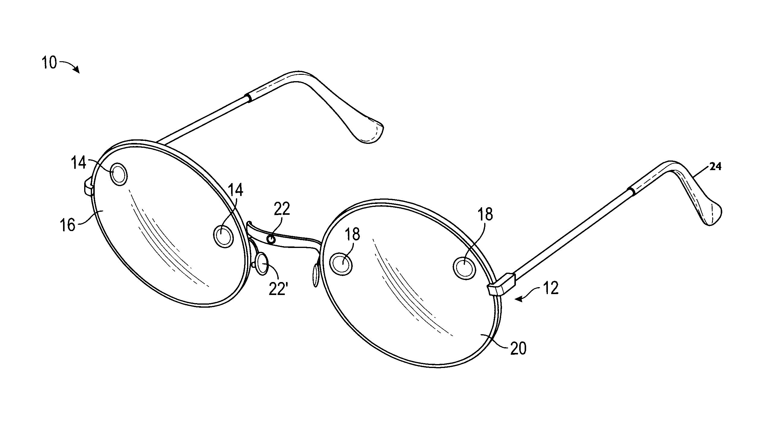
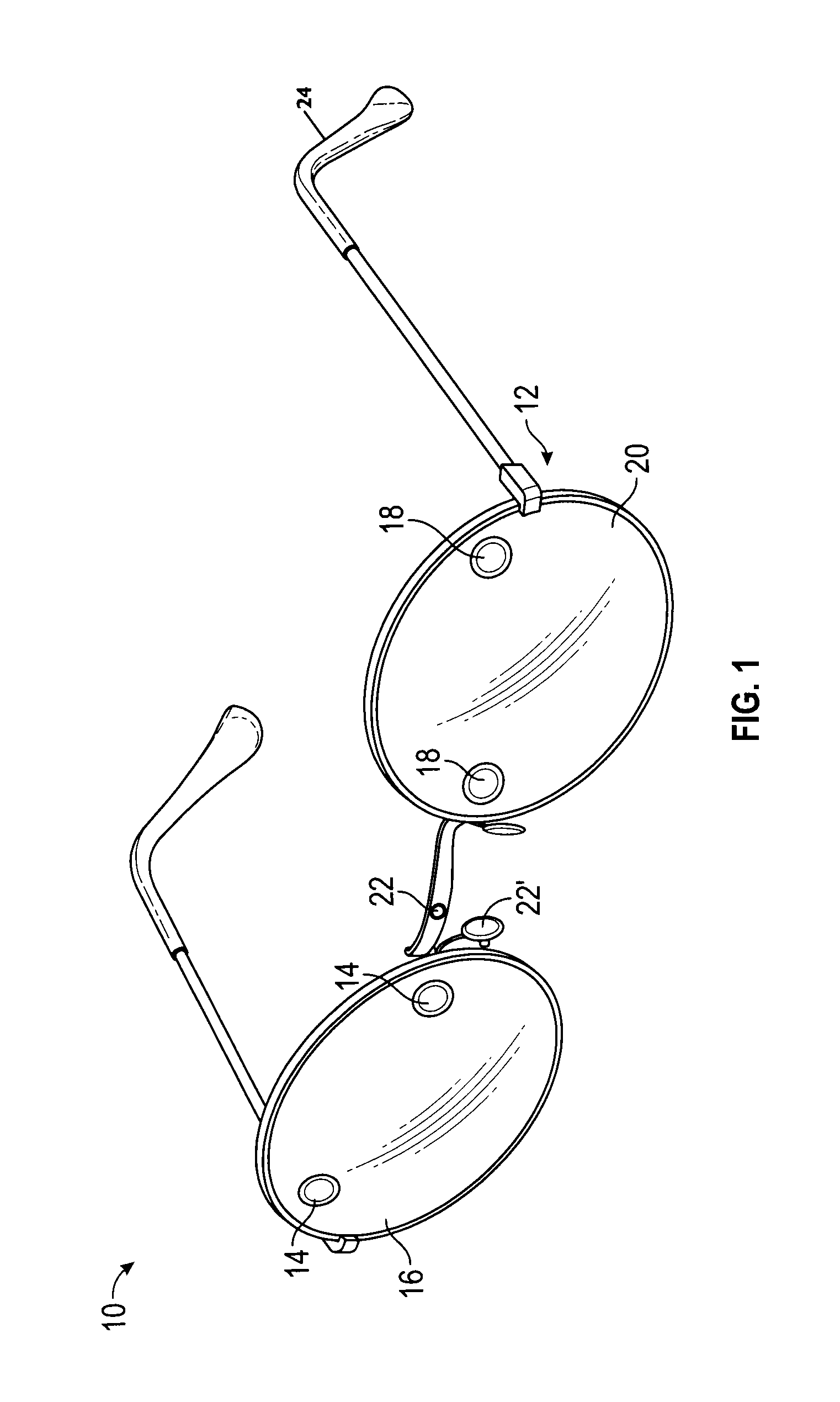
Eyewear for enhanced hearing includes a first sound detector positioned on or adjacent a first lens of the eyewear, and a second sound detector positioned on or adjacent a second lens of the eyewear. A processing unit positioned on the eyewear is in communication with the first and second sound detectors. The processing unit utilizes software that includes instructions for determining a time differential between detection of a sound by the first sound detector and detection of the same sound by the second sound detector. Because the time differential is proportional to the angular displacement of the sound from directly in front of the eyewear or person wearing the eyewear, sound signals corresponding to detected sounds having an angular displacement less than a stored maximum angular displacement value can be preferentially enhanced and transmitted via a data transmission module to a hearing aid device.

Description

CROSS REFERENCE TO RELATED APPLICATIONS AND INCORPORATION BY REFERENCE STATEMENT[0001]This application claims priority to U.S. Provisional Application No. 62 / 099,632 filed on Jan. 5, 2015, which is hereby expressly incorporated herein by reference in its entirety. This application is also a continuation-in-part of U.S. application Ser. No. 14 / 849,032 filed Sep. 9, 2015, which is a continuation of U.S. application Ser. No. 13 / 768,894 filed Feb. 15, 2013, now U.S. Pat. No. 9,161,113, which claims priority to U.S. Provisional Patent Application No. 61 / 600,236, filed Feb. 17, 2012, and U.S. Provisional Patent Application No. 61 / 624,585, filed Apr. 16, 2012. The entire contents of each are hereby expressly incorporated herein by reference.BACKGROUND OF THE INVENTIVE CONCEPTS[0002]1. Field of the Inventive Concepts[0003]The inventive concepts disclosed and claimed herein relate generally to a system for hearing aids, and more particularly, but not by way of limitation, to a hearing aid sy...

Claims


Application Information

Patent Timeline
Patent Type & Authority Applications(United States)
IPC IPC(8): H04R25/00H04R1/40H04R1/02
CPCH04R25/405H04R1/028H04R1/406H04R2430/01H04R25/554H04R2201/003H04R25/505G02C7/02G02C11/06G02C11/10G02C2202/16H04R19/005H04R19/016H04R25/552H04R2205/041
Inventor MCCRACKEN, O. WENDELL
Owner ACOUSTIC VISION
Learn More