Method of constructing an in the ear auxiliary microphone for behind the ear hearing prosthetic

a technology of auxiliary microphone and hearing prosthesis, which is applied in the field of hearing devices, can solve problems such as severe acoustic feedback, and achieve the effect of severe acoustic feedback

Inactive Publication Date: 2006-02-28
ADVANCED BIONICS AG
View PDF16 Cites 28 Cited by
  • Summary
  • Abstract
  • Description
  • Claims
  • Application Information

AI Technical Summary

Benefits of technology

[0008]The present invention addresses the above and other needs by providing an In The Ear (ITE) microphone that improves the acoustic response of a Behind The Ear (BTE) Implantable Cochlear Stimulation (ICS) system during telephone use. An acoustic seal provided by holding a telephone earpiece against the outer ear provides improved coupling of low frequency (up to about 1 KHz) sound waves, sufficient to overcome losses due to the near field acoustic characteristics resulting from the telephone microphone cooperation. In a preferred embodiment, the ITE microphone is connected to a removable ear hook of the BTE ICS system by a short bendable stalk.
[0009]In accordance with one aspect of the invention, there is provided an ITE microphone for a BTE ICS system, which microphone is placed within the concha of the ear. When a telephone handset is held against the ear, the phone seals against the outer ear, creating a chamber wherein the microphone resides. Sealing the microphone within such chamber results in improved frequency fidelity due to the sealing in of the sound pressure. Such sealing also reduces the amount of outside noise that reaches the microphone. Advantageously, the BTE ICS system does not require any earmolding to provide adequate sealing. Further, the positioning of the microphone within the ear improves hearing by using the natural acoustics of the ear.
[0012]It is a further additional feature that use of the ITE microphone does not result in chafing to the skin of the ear. The ITE microphone of the present invention includes a bendable stalk, which stalk retains a shape once the stalk is bent into that shape. The stalk may thus be bent to avoid rubbing against the skin of the ear, and the resulting chafing of the skin.

Problems solved by technology

If an ITE microphone was used in the same ear, the result would be severe acoustic feedback.

Method used


Image

  • Method of constructing an in the ear auxiliary microphone for behind the ear hearing prosthetic
  • Method of constructing an in the ear auxiliary microphone for behind the ear hearing prosthetic
  • Method of constructing an in the ear auxiliary microphone for behind the ear hearing prosthetic

Examples


Embodiment Construction

[0023]The following description is of the best mode presently contemplated for carrying out the invention. This description is not to be taken in a limiting sense, but is made merely for the purpose of describing the general principles of the invention. The scope of the invention should be determined with reference to the claims.

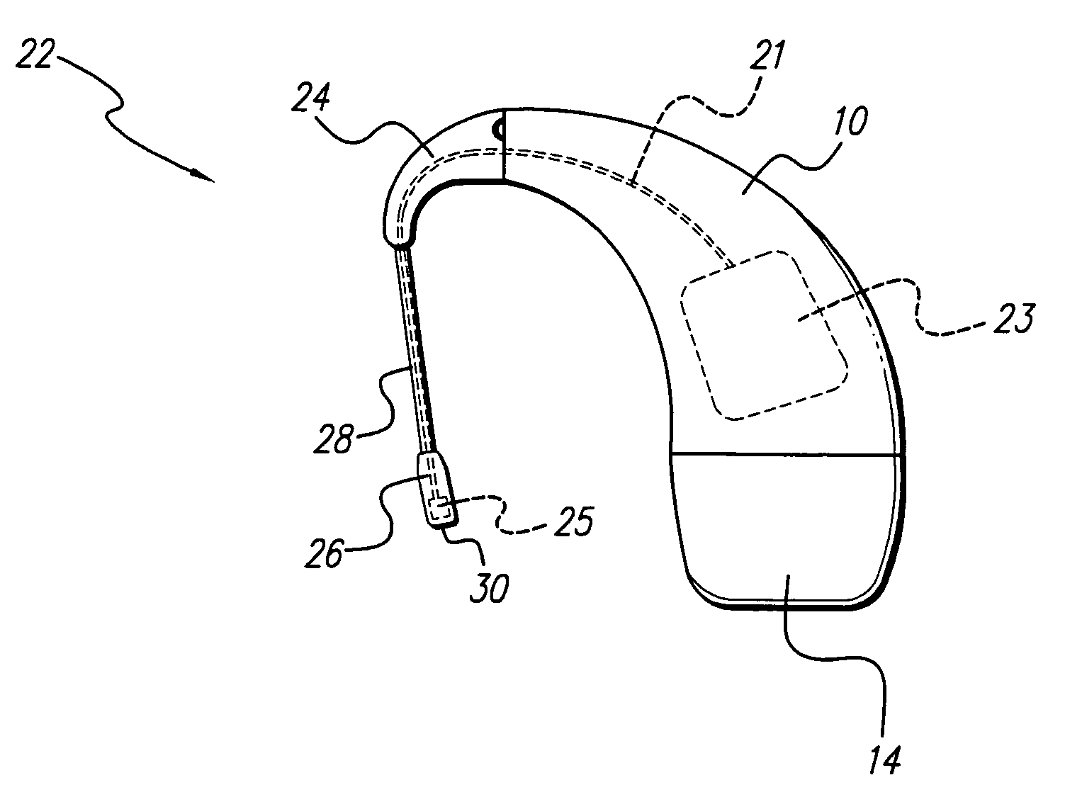
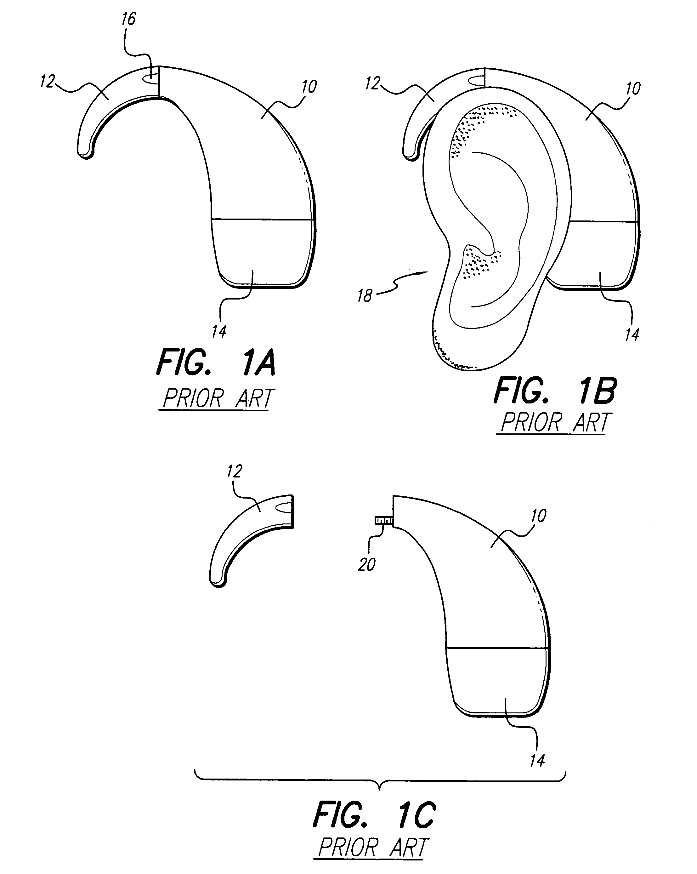
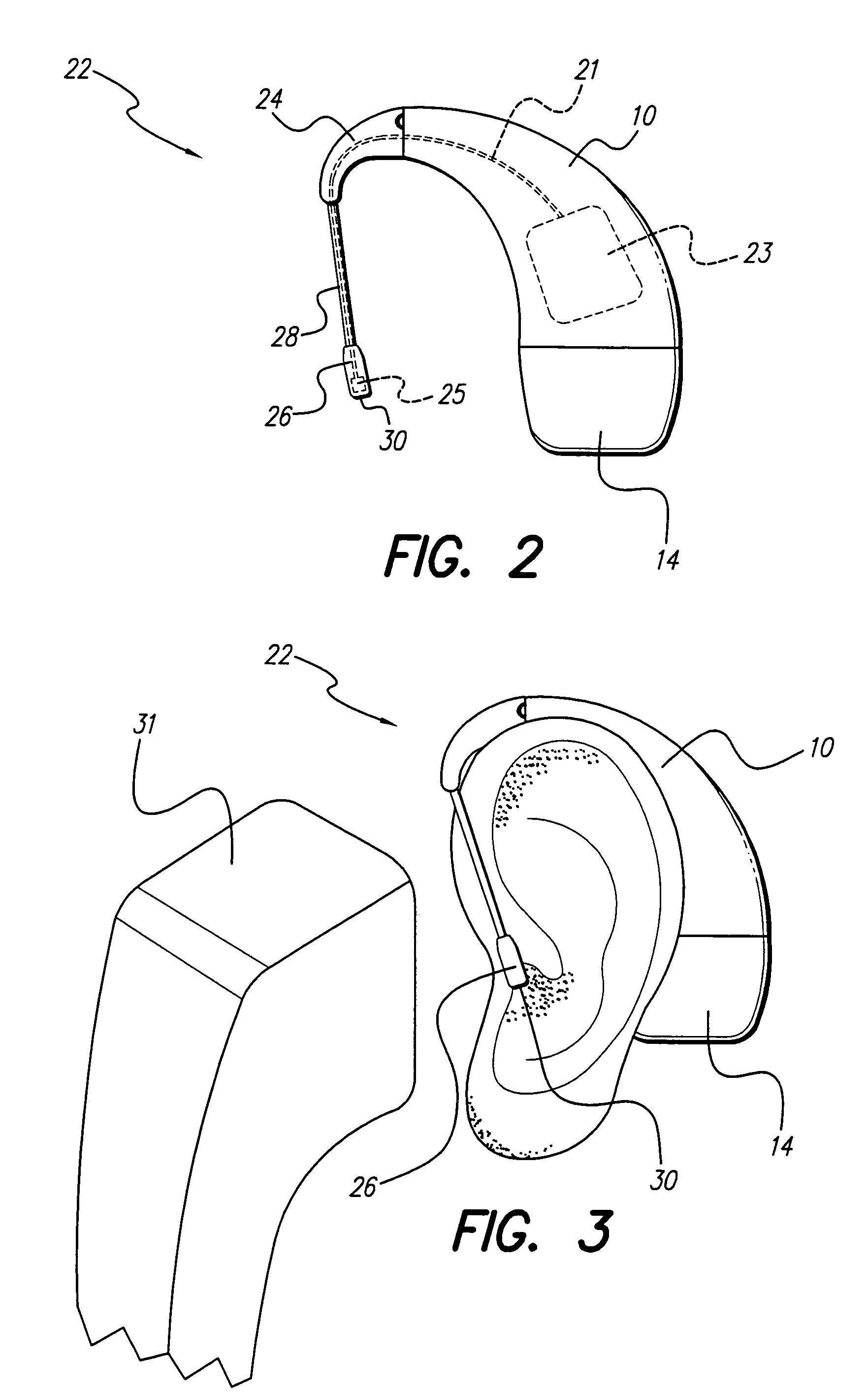
[0024]The In The Ear (ITE) microphone of the present invention improves the acoustic response of a Behind The Ear (BTE) Implantable Cochlear Stimulation (ICS) system during telephone use. As shown in FIG. 1A, when combined (or connected together), a prior art earhook 12 and BTE device 10 of an ICS system resemble a common BTE hearing aid. The earhook 12 is arched and hooks in front of the ear. The BTE device 10 continues the arch to the rear of the ear and is positioned behind the ear. A battery compartment 14 is removably attached to the bottom of the BTE device 10. Various batteries of different sizes may be interchangeably attached to the BTE device 10 de...


PUM

PropertyMeasurementUnit
volumeaaaaaaaaaa
lengthaaaaaaaaaa
diameteraaaaaaaaaa

Abstract

An In The Ear (ITE) microphone improves the acoustic response of a Behind The Ear (BTE) Implantable Cochlear Stimulation (ICS) system during telephone use. An acoustic seal provided by holding a telephone earpiece against the ear provides improved coupling of low frequency (up to about 1 KHz) sound waves, sufficient to overcome losses due to the near field acoustic characteristics common to telephones. In a preferred embodiment, the ITE microphone is connected to a removable ear hook of the BTE ICS system by a short bendable stalk.

Description

[0001]The present application is a Divisional of U.S. application Ser. No. 09 / 927,130, filed Aug. 10, 2001 now U.S. Pat. No. 6,775,389, which application is incorporated herein by reference in its entirety.BACKGROUND OF THE INVENTION[0002]The present invention relates to hearing devices for aiding the hearing impaired and the profoundly deaf, and more particularly to an In The Ear (ITE) auxiliary microphone connected to a Behind The Ear (BTE) speech processor through a removable ear hook. The microphone of the present invention is especially useful for a user conversing over a telephone.[0003]Implantable Cochlear Stimulation (ICS) systems are known in the art. Such systems are used to help the profoundly deaf (those whose middle and / or outer ear is dysfunctional, but whose auditory nerve remains intact) to hear. The sensation of hearing is achieved by directly exciting the auditory nerve with controlled impulses of electrical current, which impulses are generated as a function of pe...

Claims


Application Information

Patent Timeline
Patent Type & Authority Patents(United States)
IPC IPC(8): H01R43/00A61N1/36H04R25/00
CPCA61N1/36032H04R25/456H04R25/48Y10T29/49176Y10T29/49117Y10T29/49174Y10T29/49178H04R2225/67A61N1/36038
Inventor CRAWFORD, SCOTT A.FERNALD, C. GEOFFREY E.
Owner ADVANCED BIONICS AG
Why Eureka
Try Eureka