Method of Making a Spanner

Active Publication Date: 2016-06-09
CHEN MING CHANG +1
View PDF6 Cites 11 Cited by
  • Summary
  • Abstract
  • Description
  • Claims
  • Application Information

AI Technical Summary

Benefits of technology

[0006]An object of this invention is to provide a method of making a spanner which reduces t

Problems solved by technology

However, such heating method requires a high cost for processing with correlated heating machines.
Further, the heated blank al can only be shaped after the cooling step 15 is done, and this requires more complicated actions and takes much

Method used


Image

  • Method of Making a Spanner
  • Method of Making a Spanner
  • Method of Making a Spanner

Examples


Embodiment Construction

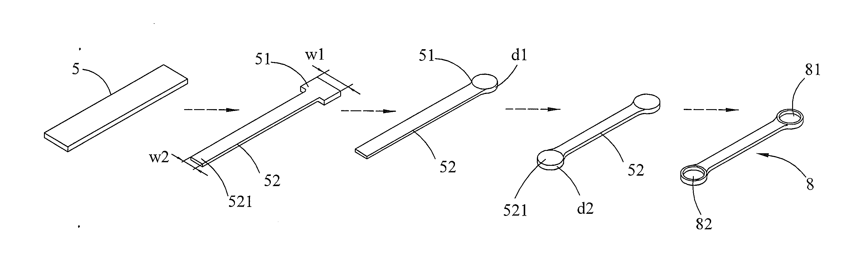
[0028]Referring to FIG. 5 and FIG. 6-1, a method 4 of a first preferred embodiment of this invention for making a spanner 8 comprises a preparing step 41, an initial forging step 42, a first end stamping step 43, a second end stamping step 44 and a trimming step 45. The preparing step 41 prepares a flat metal blank 5. Herein, the flat metal blank 5 has a shape with four straight sides. It can be especially rectangular in shape as shown. As used herein, a width of the flat metal blank 5 at least equals a maximum outer diameter of the finished spanner 8, and a thickness of the flat metal blank 5 equals a thickness of the finished spanner 8. The initial forging step 42 forges and presses a part of the flat metal blank 5. In this step, the initial forging step 42 subjects a part of the flat metal blank 5 to compressive forces. Therefore, a head 51 and a shank 52 extended outwards from the head 51 are formed into a T-shaped contour. Specifically, the head 51 is formed at one end of the f...


PUM


Abstract

A method of making a spanner comprises the steps of preparing a flat metal blank, forging and pressing a part of the metal blank to form a head and a shank whose width is smaller than a width of the head, pressing the head to form a first arch-shaped part, pressing a shank end of the shank to expand the shank end and thence form a second arch-shaped part, and pressing the head and the shank end again to remove redundant scrap projecting from the first arch-shaped part and the second arch-shaped part and also punch finished holes in the head and the shank end respectively, thereby completing the finished spanner. Accordingly, the method reduces the waste of the material and the processing cost, decreases the use frequency of high-cost machines and promotes the processing efficiency by using the flat metal blank.

Description

BACKGROUND OF THE INVENTION[0001]1. Field of the Invention[0002]This invention relates to a spanner shaping method and relates particularly to a method of making a spanner capable of reducing the waste of the material, shortening the processing time and decreasing the cost.[0003]2. Description of the Related Art[0004]Referring to FIG. 1 and FIG. 2, a traditional method 1 of making a spanner Si is carried out by hot forging. The method 1 comprises a preparing step 11, a cutting step 12, a heating step 13, a punching step 14, a cooling step 15 and a removing step 16. The preparing step 11 prepares a rolled round metal blank a. The cutting step 12 cuts the blank a into a proper length. The heating step 13 applies a heater 131 providing a fixed and high temperature to heat and soften the blank a. A punch 141 and dies 142 disposed on the punch 141 and provided with a shaping impress are used in the punching step 14. The punching step 14 puts the heated and softened blank a on the dies 14...

Claims


Application Information

Patent Timeline
IPC IPC(8): B21K5/16
CPCB21K5/16
Inventor CHEN, MING-CHANGLIAO, MAO-CHIH
Owner CHEN MING CHANG
Why Eureka
Try Eureka