Acoustical structure

a technology of acoustic structures and acoustic panels, applied in the field of acoustic structures, can solve the problems of increasing installation costs, adding cost and weight, and heavy and complex construction of acoustic panels, and achieve the effect of reducing capital and installation costs and high nrc values

Active Publication Date: 2016-06-09
AWI LICENSING
View PDF14 Cites 8 Cited by
  • Summary
  • Abstract
  • Description
  • Claims
  • Application Information

AI Technical Summary

Benefits of technology

[0007]The first and second scrim layers of the substrate are engineered and configured in some embodiments to have an airflow resistance that allow the honeycomb substrate to achieve high NRC values. The airflow resistance of each of the first and second scrim layers may be controlled by any combination of the following: (1) specialty paint coating techniques; (2) adhesive coating techniques; and/or (3) tightness (i.e. porosity) of the scrim layer. The first and second scrim layers can be woven or nonwoven scrims, depending on desired visual aesthetic and impact. Advantageously, the use of scrims having properly engineered airflow resistance eliminates the need for a layer having perforations formed therein, and can be designed to be “acousticly transparent” and “optically opaque.

Problems solved by technology

These acoustical panels are preferably self-supporting; however, such acoustical panels may sometimes be heavy and complex constructions to achieve a high NRC value.
The sound absorbing materials may then require a heavy perime

Method used


Image

  • Acoustical structure
  • Acoustical structure
  • Acoustical structure

Examples


Embodiment Construction

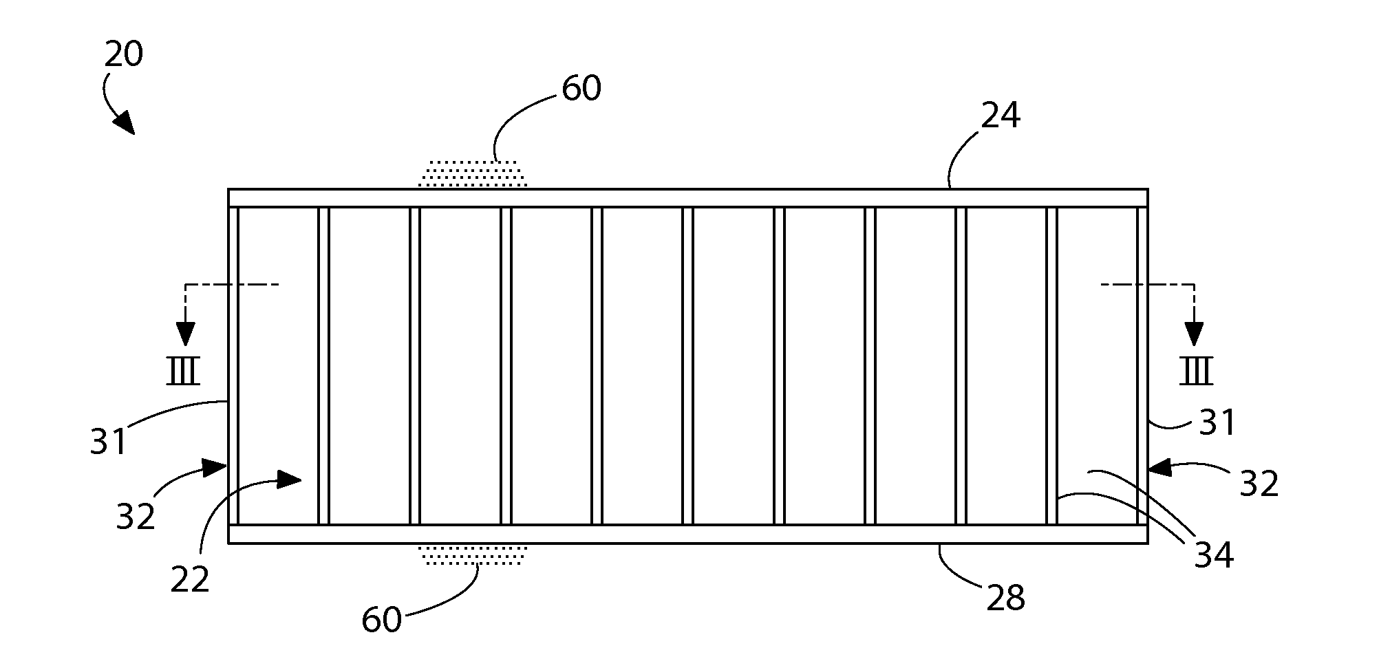
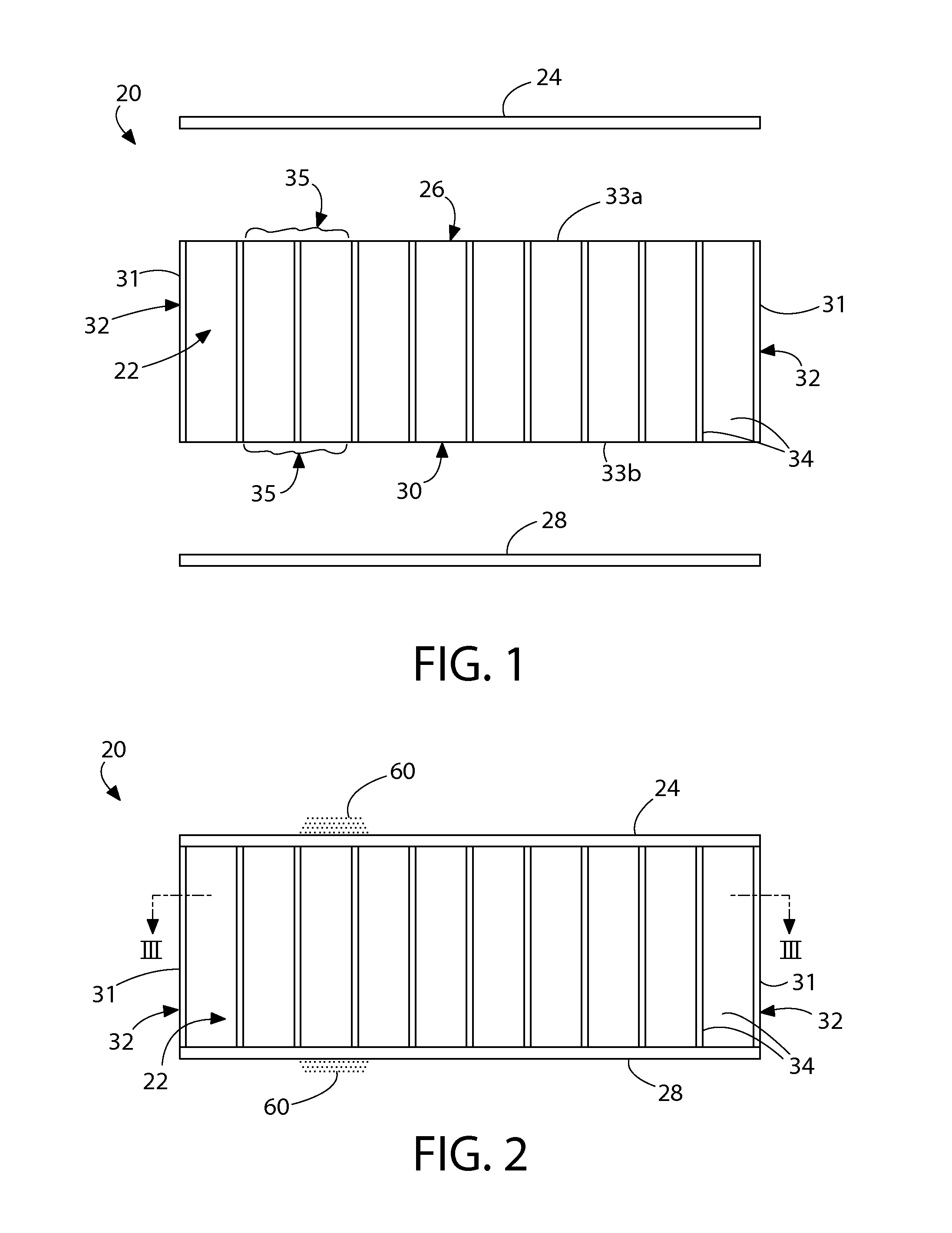
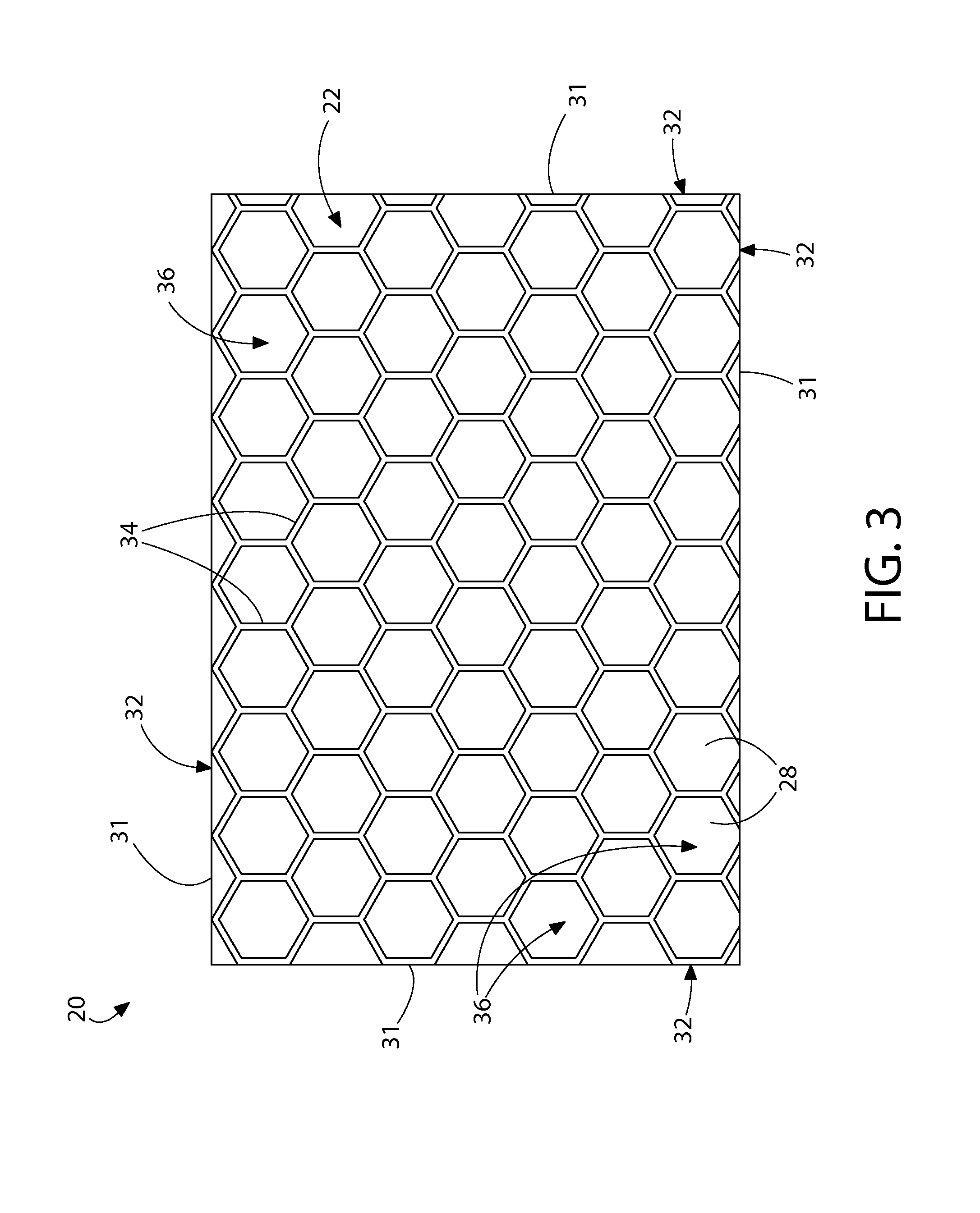
[0023]The features and benefits of the invention are illustrated and described herein by reference to exemplary embodiments. This description of exemplary embodiments is intended to be read in connection with the accompanying drawings, which are to be considered part of the entire written description. In the description of embodiments disclosed herein, any reference to direction or orientation is merely intended for convenience of description and is not intended in any way to limit the scope of the present invention. Relative terms such as “lower,”“upper,”“horizontal,”“vertical,”, “above,”“below,”“up,”“down,”“top” and “bottom” as well as derivative thereof (e.g., “horizontally,”“downwardly,”“upwardly,” etc.) should be construed to refer to the orientation as then described or as shown in the drawing under discussion. These relative terms are for convenience of description only and do not require that the apparatus be constructed or operated in a particular orientation. Terms such as...


PUM

PropertyMeasurementUnit
Thicknessaaaaaaaaaa
Massaaaaaaaaaa
Fractionaaaaaaaaaa

Abstract

A light-weight acoustical substrate is disclosed. In one embodiment, the substrate includes a substantially open core and outer facing layers. The core is comprised of a plurality of open, cells which extend between the facing layers. The cells may have numerous configurations, including honeycomb. The facing layers may be non-woven or woven glass scrims in some embodiments, A multi-layered acoustical structure is provided which in one non-limiting embodiment is comprised of two cores with outer facing layers and an interlayer between the cores.

Description

FIELD OF THE INVENTION[0001]The present invention relates to acoustical structures, and more particularly to light-weight acoustical structures characterized by a high noise reduction coefficient.BACKGROUND OF THE INVENTION[0002]Acoustical substrates are used in a variety of noise reduction applications inside a building structure to create sound controlled room environments. The substrates may be formed into acoustical panels that can be applied to the walls, ceilings (in some instances forming a suspended ceiling system), and acoustical sound treatments or canopies. Acoustical panels with a high noise reduction coefficient (NRC) as established by testing standards such as ASTM C423 (reverberation room method) or ASTM C384 (impedance tube method) are desirable. The NRC provides a relative measure of the percentage of sound that an acoustical structure will absorb versus reflect. An NRC value equal to or greater than 0.65 to 1.0 is generally considered a high NRC, which ideally indi...

Claims


Application Information

Patent Timeline
IPC IPC(8): B32B3/12B32B15/04B32B17/06B32B5/02B32B13/08
CPCB32B3/12B32B5/024B32B5/022B32B2307/102B32B17/06B32B15/04B32B13/08B32B17/02E04B1/82E04B1/99G10K11/16
Inventor OLESKE, PETER J.
Owner AWI LICENSING
Why Eureka
Try Eureka