Sensor output value estimation device

a technology of output value and estimation device, which is applied in the direction of electrical control, instruments, heat measurement, etc., can solve problems such as inability to carry out control properly

Inactive Publication Date: 2016-06-09
ISUZU MOTORS LTD +1
View PDF14 Cites 7 Cited by
  • Summary
  • Abstract
  • Description
  • Claims
  • Application Information

AI Technical Summary

Benefits of technology

[0008]According to a sensor output value estimation device disclosed herein, a sensor output value that reflects a response delay of a temperature sensor can be estimated effectively.

Problems solved by technology

When a temperature sensor malfunctions due to its fault or the like, such controls may not be carried out properly.

Method used


Image

  • Sensor output value estimation device
  • Sensor output value estimation device
  • Sensor output value estimation device

Examples


Embodiment Construction

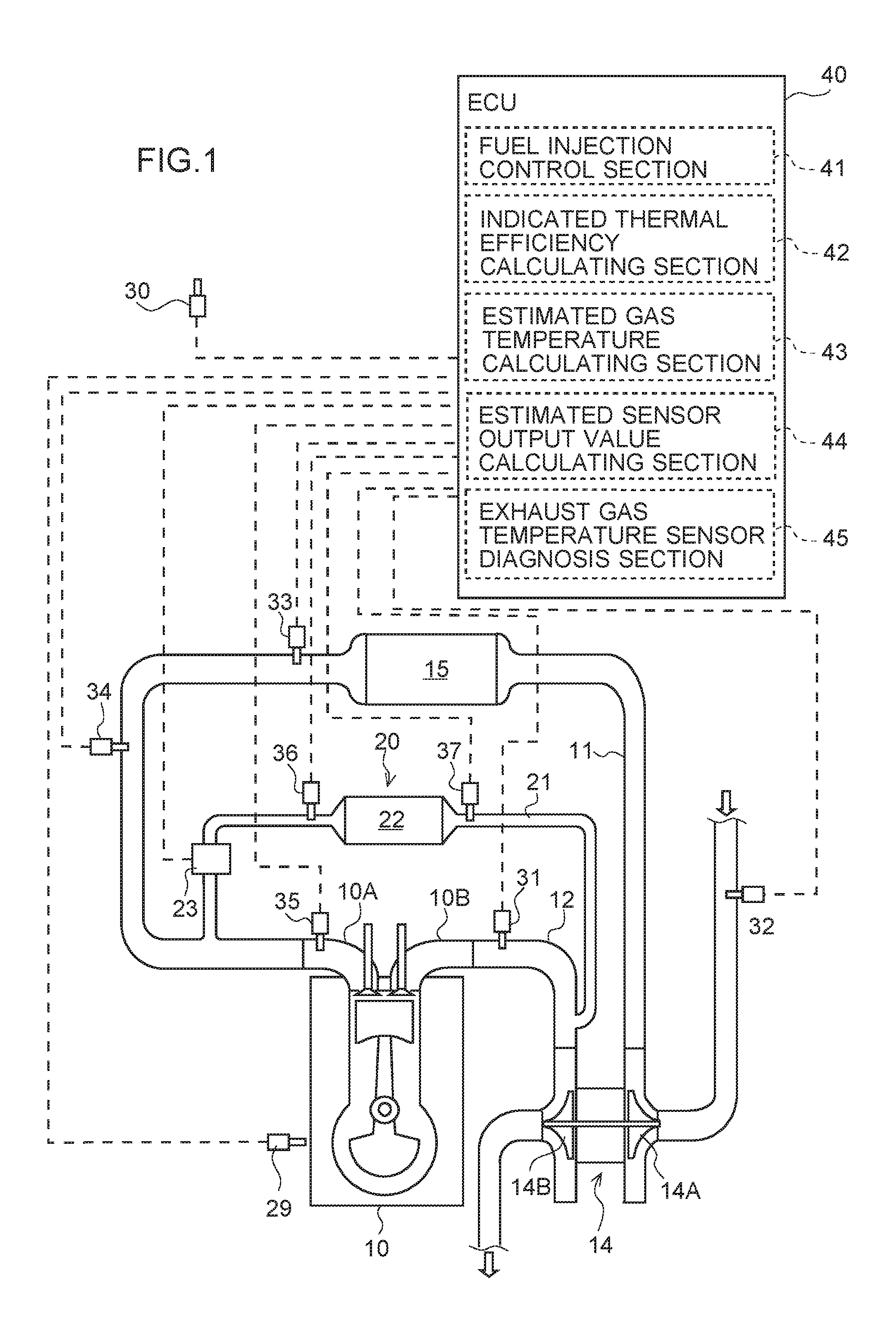
[0012]Hereinafter, a sensor output value estimation device according to an embodiment of the present invention will be described with reference to FIGS. 1 to 3. Identical parts are given identical reference numerals and symbols, and their names and functions are identical as well. Therefore, detailed description of such parts will not be repeated.

[0013]As illustrated in FIG. 1, a diesel engine (hereinafter simply referred to as “engine”) 10 has an intake manifold 10A and an exhaust manifold 10B. The intake manifold 10A is connected to an intake passage (intake pipe) 11 for introducing fresh air, and the exhaust manifold 10B is connected to an exhaust passage (exhaust pipe) 12 for discharging an exhaust gas to the atmosphere.

[0014]The exhaust passage 12 has an exhaust gas temperature sensor 31, a turbine 14B of a turbo charger 14, and an exhaust gas aftertreatment device (not illustrated). The exhaust gas temperature sensor is located upstream of the turbine, and the turbine is locat...


PUM

PropertyMeasurementUnit
gas temperatureaaaaaaaaaa
temperatureaaaaaaaaaa
thermal efficiencyaaaaaaaaaa

Abstract

A sensor output value estimation device that effectively estimates sensor output values reflecting a response delay of a temperature sensor. The device includes an estimated gas temperature calculation unit for calculating an estimated gas temperature of an engine on a basis of at least a running condition of the engine and a state quantity of the gas in the engine. The device also includes an estimated sensor output value calculation unit for calculating an estimated sensor output value reflecting the response delay of the temperature sensor on a basis of the calculated estimated gas temperature and a pre-stored first model formula specifying a relation among the temperature change time constant of the temperature sensor, the gas flow rate, and the gas temperature.

Description

TECHNICAL FIELD[0001]The present invention relates to a sensor output value estimation device, and relates in particular to estimating a sensor output value that reflects a response delay of a sensor.BACKGROUND ART[0002]Temperature sensors are used in controls of an aftertreatment device for purifying an exhaust gas from an engine, an exhaust gas recirculation (hereinafter referred to as “EGR”) device for partially recirculating the exhaust gas into an intake system, and other elements. When a temperature sensor malfunctions due to its fault or the like, such controls may not be carried out properly.[0003]In light of this problem, there is known a technique in which malfunctioning of a temperature sensor is detected by comparing an estimated gas temperature, which is estimated on the basis of the running condition of the engine, with a sensor value of the temperature sensor (see, for example, PATENT LITERATURE DOCUMENT 1).LISTING OF REFERENCES[0004]PATENT LITERATURE DOCUMENT 1: Japa...

Claims


Application Information

Patent Timeline
Patent Type & Authority Applications(United States)
IPC IPC(8): F02D41/14G01K7/42
CPCF02D41/1447G01K2205/04G01K7/42
Inventor HANAWA, SATOSHIIKAI, YOSHIAKI
Owner ISUZU MOTORS LTD
Why Eureka
Try Eureka