
Optical fiber ribbon and optical fiber cable housing optical fiber ribbon

a technology of optical fiber ribbon and optical fiber cable, which is applied in the direction of optical fiber, fibre mechanical structure, instruments, etc., can solve the problems of difficult removal of ultraviolet curable resin, difficult intermediate branching operation, and difficulty in removing particular optical fibers from other optical fibers, so as to reduce the diameter of optical fibers, reduce the outer diameter dimension, and easy to bend

Inactive Publication Date: 2016-06-09
THE FUJIKURA CABLE WORKS LTD +1
View PDF13 Cites 37 Cited by
  • Summary
  • Abstract
  • Description
  • Claims
  • Application Information

AI Technical Summary

Benefits of technology

The present invention provides an optical fiber ribbon that can achieve higher density and reduction in diameter. The intermittent fixing structure of the ribbon allows for easy bending and a larger number of optical fibers can be housed in the cable, improving packaging density. Additionally, the distance between the centers of adjacent optical fibers is set to equal a distance between the centers of adjacent optical fibers in a commonly distributed ribbon, ensuring accurate placement in the fusion machine without falling out of the V-shaped grooves. This results in a more reliable and efficient optical fiber cable.

Problems solved by technology

With the optical fiber ribbon described in Patent Literature 1, however, an intermediate branching operation is difficult when laying optical fibers into residences of subscribers.
Since the entire circumference of the plural optical fibers is covered with the ultraviolet curable resin, the removal of the ultraviolet curable resin is difficult and the particular optical fibers are not easily removed from the other optical fibers.
However, when the optical fiber ribbon described in Patent Literature 1 is fused and connected with another optical fiber ribbon, bare optical fibers (glass optical fibers) from which the cover layer made of resin is removed may be hard to be set in a fusion machine having plural V-shaped grooves formed at a predetermined pitch to be independently placed in the V-shaped grooves.
Failure in placing the optical fibers in the V-shaped grooves in the fusion machine requires extra work to forcibly place the optical fibers in the V-shaped grooves.

Method used


Image

  • Optical fiber ribbon and optical fiber cable housing optical fiber ribbon
  • Optical fiber ribbon and optical fiber cable housing optical fiber ribbon
  • Optical fiber ribbon and optical fiber cable housing optical fiber ribbon

Examples


example

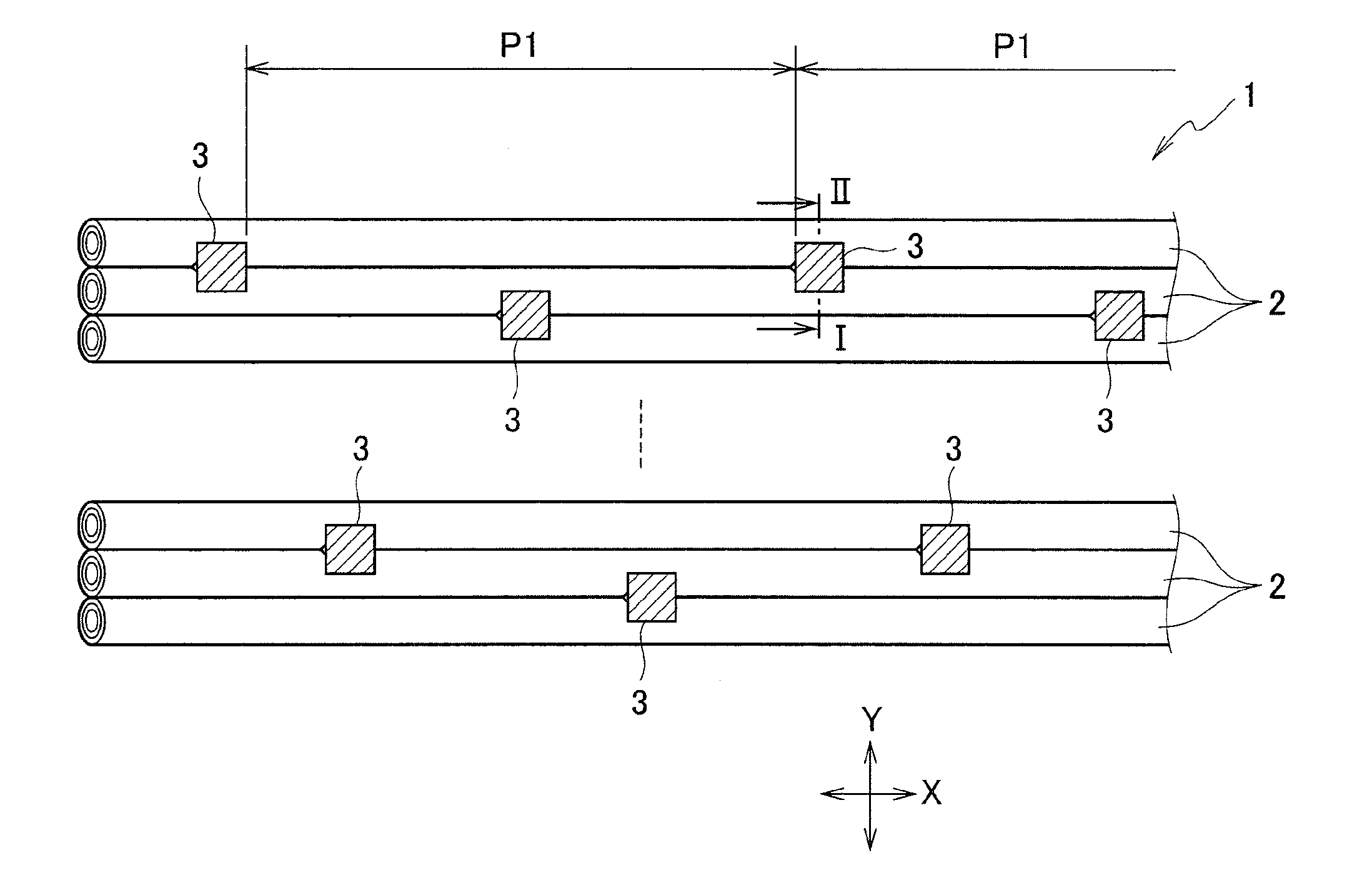
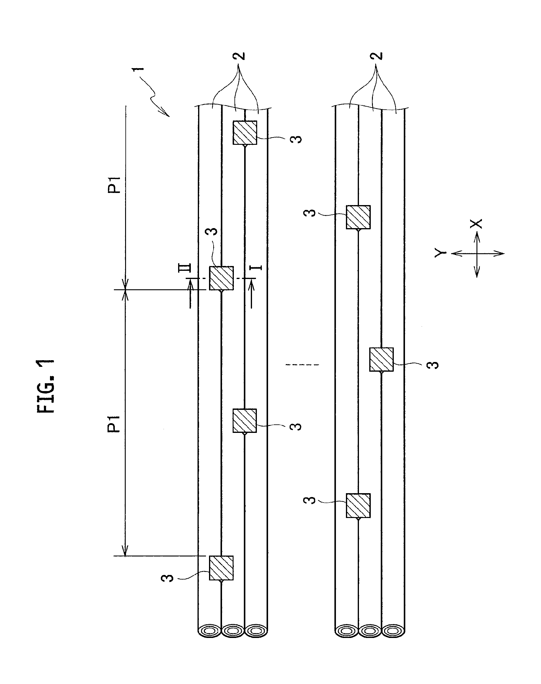
[0038]Several types of optical fibers having different outer diameter dimensions were used in which the distance between the centers of adjacent optical fibers varied, so as to manufacture optical fiber ribbons (4-core ribbons). The manufacture of connecting portions and unconnected portions employed the method disclosed in Japanese Unexamined Patent Application Publication No. 2010-033010 (Japanese Patent Application No. 2009-082778). The pitch adjustment between the optical fibers employed the method disclosed in Japanese Unexamined Patent Application Publication No. 08-146239 (Japanese Patent Application No. 06-163292). Note that all optical fibers in one optical fiber ribbon have the same outer diameter dimension.

[0039]Next, batch fusion splicing performance was evaluated when one optical fiber ribbon thus obtained was entirely fused with the other optical fiber ribbon. The operation process was as follows. First, the optical fiber ribbon was held with a holder, the first cover ...


PUM


Abstract

Provided is an optical fiber ribbon capable of achieving higher density and reduction in diameter and accurately placing optical fibers in V-shape grooves in a fusion machine without failure. The optical fiber ribbon 1 includes three or more of optical fibers 2 arranged in parallel and connecting portions 3 connecting adjacent two optical fibers 2 together, the connecting portions 3 being intermittently provided in each of a ribbon longitudinal direction and a ribbon width direction. The connecting portions 3 are each formed in such a manner as to fill resin into a gap S formed between adjacent two optical fibers 2, and both surfaces of the respective connecting portions 3 are each formed into a recess having a concave shape curved toward a center of the gap S to separate from lines 4,5 each connecting contact points of the optical fibers 2 when being placed on a horizontal surface.

Description

CROSS-REFERENCE TO RELATED APPLICATION[0001]The application is a Continuation of PCT Application No. PCT / JP2012 / 076590, filed on Oct. 15, 2012, and claims the benefit of priority from the prior Japanese Patent Application No. 2011-229066, filed on Oct. 18, 2011, the entire contents of which are incorporated herein by reference.BACKGROUND OF THE INVENTION[0002]The present invention relates to an optical fiber ribbon having an intermittent fixing structure in which adjacent optical fibers are intermittently connected together via connecting portions, and relates to an optical fiber cable housing the optical fiber ribbon.[0003]There has been an increased demand for higher density and reduction in diameter in the technical field of optical fiber cables. As an example of a method for achieving higher density and reduction in diameter, there is proposed a method for reducing the outer diameter of optical fibers from 250 μm, which is a presently-used size, to 200 μm or smaller (for example...

Claims


Application Information

Patent Timeline
Patent Type & Authority Applications(United States)
IPC IPC(8): G02B6/44
CPCG02B6/4404G02B6/448G02B6/4482G02B6/4403G02B6/3636G02B6/2555G02B6/4489G02B6/2551G02B6/441G02B6/4405G02B6/443
Inventor NAMAZUE, AKIRAOSATO, KENOKADA, NAOKIYAMADA, YUSUKEKAKUTA, DAISUKENAKANE, HISAAKIHAMAGUCHI, SHINYA
Owner THE FUJIKURA CABLE WORKS LTD
Features
  • Generate Ideas
  • Intellectual Property
  • Life Sciences
  • Materials
  • Tech Scout
  • Unparalleled Data Quality
  • Higher Quality Content
  • 60% Fewer Hallucinations
Learn More