Integrated circuit assemblies with rigid layers used for protection against mechanical thinning and for other purposes, and methods of fabricating such assemblies

a technology of integrated circuits and rigid layers, which is applied in the direction of semiconductor devices, semiconductor/solid-state device details, electrical devices, etc., can solve the problems of inconvenient assembly of rigid layers, inability to meet the requirements of mechanical thinning, so as to facilitate the handling of thin interposers and reduce interposer breakage and warpage

Active Publication Date: 2016-06-09
INVENSAS CORP
View PDF8 Cites 37 Cited by
  • Summary
  • Abstract
  • Description
  • Claims
  • Application Information

AI Technical Summary

Benefits of technology

[0016]Advantageously, lower layer 410 may have a CTE that matches the interposer 120 and / or die 110 better than encapsulant 160. (The CTE of interest is primarily in the XY plane, i.e. along the plane of the interposer; all the CTEs in this disclosure are at room temperature unless noted otherwise.) Many polymeric encapsulants have high XY CTEs, possibly 10 ppm / ° K or higher, and such CTEs are considerably higher than of many materials commonly used for interposer substrates 120S and for the die's substrates (not shown). For example, the interposer's and die's substrates can be inorganic semiconductor materials, with CTEs below 8 ppm / ° K (2.6 ppm / ° K for silicon). Interposers' substrates can be glasses or ceramics with XY CTE under 5 ppm / ° K (though some glasses and ceramics have higher CTEs). While organic polymer CTEs can be lowered by fillers, such low CTEs change other encapsulant properties (e.g. increase rigidity) and thus undesirably limit encapsulant choices. In contrast, some rigid materials suitable for layer 410 (including silicon oxide, aluminum oxide, and some other inorganic materials) have lower CTEs. If interposer substrate 120S is made of semiconductor or some other low-CTE material, then layer 410 can be CTE-matched to the interposer and the die without losing the soft cushion of encapsulant 160.
[0018]The multi-layer structures such as 410 / 160 can be used for purposes other than reduced dishing, even if there is no need to reduce dishing, and even when the interposer thinning does not include a mechanical process. The multi-layered encapsulant stiffens the interposer while providing the compliant cushion on top, and this can be useful for example to facilitate thin interposer handling and reduce interposer breakage and warpage. Thus, U.S. Pat. No. 8,841,752 issued Sep. 23, 2014 to Chaware et al. describes stiffening an interposer wafer in which multiple interposers are manufactured; the wafer is stiffened by widening the scribe lines between the adjacent interposers and forming a stiffener on the scribe lines. In some embodiments of the present invention, the interposer wafer is stiffened by layer 410 without widening the scribe lines. In another example, described in US pre-grant patent publication no. 2013 / 0070437 A1 (Mar. 21, 2013, inventor: Mohammed et al.) an interposer is stiffened by a stiffening layer pierced by vias 130. As described above, according to some embodiments of the present invention, the interposer is stiffened without running the vias 130 through layer 410. However, some embodiments of the present invention can be used together with the techniques described in U.S. Pat. No. 8,841,752 and / or 2013 / 0070437 and / or with other techniques.

Problems solved by technology

However, a thin substrate is fragile and, in addition, is easily warped by internal and external stresses, e.g. thermal stresses.
As is known, carrier wafer attachment and removal is a problematic process that requires a suitable adhesive to glue the carrier wafer to the interposer and then to allow removal of the carrier wafer without leaving a residue or damaging the RDL.
While organic polymer CTEs can be lowered by fillers, such low CTEs change other encapsulant properties (e.g. increase rigidity) and thus undesirably limit encapsulant choices.

Method used


Image

  • Integrated circuit assemblies with rigid layers used for protection against mechanical thinning and for other purposes, and methods of fabricating such assemblies
  • Integrated circuit assemblies with rigid layers used for protection against mechanical thinning and for other purposes, and methods of fabricating such assemblies
  • Integrated circuit assemblies with rigid layers used for protection against mechanical thinning and for other purposes, and methods of fabricating such assemblies

Examples


Embodiment Construction

[0026]The embodiments described in this section illustrate but do not limit the invention. In particular, the invention is not limited to specific processes, dimensions, and other features except as defined by the appended claims.

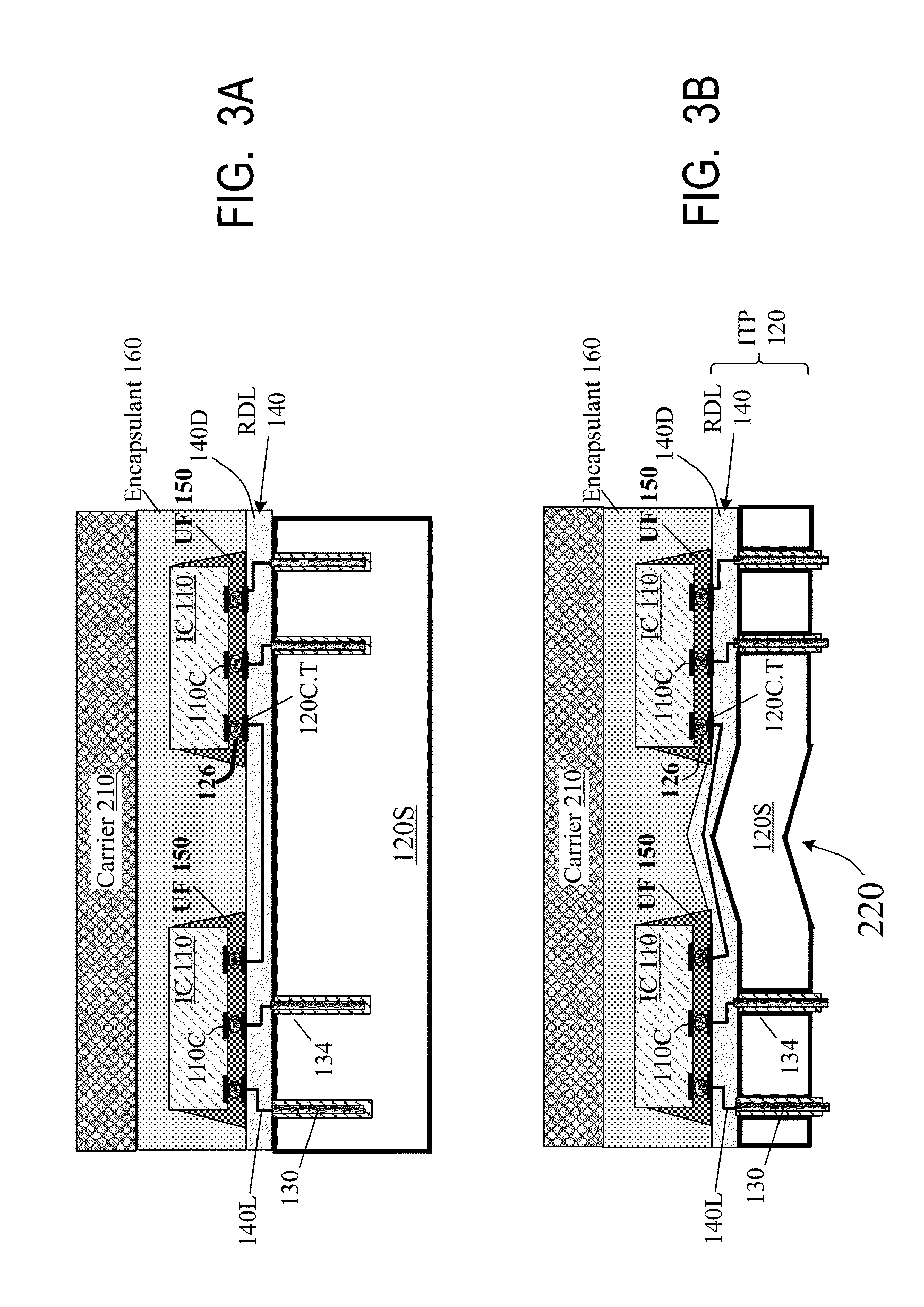
[0027]FIG. 5 is a flowchart of an exemplary fabrication process for some embodiments of the present invention including some embodiments illustrated in FIG. 4B. Interposer fabrication starts with a substrate 120S which can be sufficiently thick to meet the strength, heat dissipation, and possibly other fabrication requirements. In some examples, substrate 120S is a wafer in which multiple interposers are fabricated at the same time. The interposer wafer can be singulated into individual interposers before or after attachment of die 110 to the interposers. For example, multiple assemblies can be fabricated as a single structure based on a single interposer wafer, and each assembly can be as in FIG. 4B or some other type. The multiple-assembly structure can b...


PUM


Abstract

Die (110) and / or undiced wafers and / or multichip modules (MCMs) are attached on top of an interposer (120) or some other structure (e.g. another integrated circuit) and are covered by an encapsulant (160). Then the interposer is thinned from below. Before encapsulation, a layer (410) more rigid than the encapsulant is formed on the interposer around the die to reduce or eliminate interposer dishing between the die when the interposer is thinned by a mechanical process (e.g. CMP). Other features are also provided.

Description

CROSS REFERENCE TO RELATED APPLICATIONS[0001]The present application claims priority of U.S. provisional patent application No. 62 / 087,361, filed 4 Dec. 2014, incorporated herein by reference.BACKGROUND OF THE INVENTION[0002]The present invention relates to semiconductor integrated circuits (ICs), and more particularly to assemblies of multiple ICs.[0003]FIG. 1 illustrates a typical assembly with multiple ICs 110 connected to a printed circuit board (PCB) 114. Each IC 110 is a die initially fabricated with other die as part of a larger wafer but then separated from the wafer. Oftentimes, die 110 are not attached to the PCB directly because PCB contact pads 114C cannot be spaced as closely from each other as the die's contact pads 110C due to coarser PCB fabrication technologies. Therefore, the die are attached to the PCB through an interposer (ITP) 120; the interposer's top contact pads 120C.T match the die's contact pads 110C, and the interposer's bottom contact pads 120C.B match t...

Claims


Application Information

Patent Timeline
Patent Type & Authority Applications(United States)
IPC IPC(8): H01L23/538H01L25/00H01L23/00H01L25/065
CPCH01L23/5385H01L24/83H01L25/50H01L25/0655H01L23/3128H01L23/3135H01L21/486H01L2924/181H01L2224/32225H01L2224/48091H01L2224/48137H01L2224/73204H01L2924/15192H01L2924/15311H01L2224/32106H01L2224/32105H01L24/05H01L24/08H01L24/16H01L24/32H01L21/6835H01L24/48H01L24/49H01L25/0657H01L2224/0401H01L2224/05644H01L2224/05647H01L2224/05655H01L2224/08225H01L2224/16227H01L2224/48101H01L2224/48105H01L2224/48227H01L2924/15153H01L2924/18161H01L2224/49097H01L2924/00014H01L25/0652H01L2221/68331H01L23/147H01L23/15H01L23/49827H01L2924/351H01L2924/3511H01L2924/00012H01L2224/16225H01L2924/00H01L2224/45015H01L2924/207H01L2224/45099
Inventor GAO, GUILIANUZOH, CYPRIAN EMEKAWOYCHIK, CHARLES G.SHEN, HONGSITARAM, ARKALGUD R.WANG, LIANGAGRAWAL, AKASHKATKAR, RAJESH
Owner INVENSAS CORP
Why Eureka
Try Eureka