
Molding apparatus and method for producing articles molded through sequential injection

a technology of sequential injection and molding apparatus, which is applied in the direction of auxillary shaping apparatus, domestic articles, applications, etc., can solve the problems of anti-aesthetic surface defects on the molded pieces, and achieve the effects of eliminating the surface defects of the molded pieces, reducing pressure, and uniform pressur

Active Publication Date: 2016-06-16
INGLASS SPA
View PDF2 Cites 14 Cited by
  • Summary
  • Abstract
  • Description
  • Claims
  • Application Information

AI Technical Summary

Benefits of technology

The objective of this patent is to improve the quality of molded articles by making the pressure in the mold cavity more uniform and regular during the filling and packing steps. This results in better aesthetic quality, reduces surface defects caused by pressure lines, and reduces the amount of material needed to construct the mold, without causing bowing.

Problems solved by technology

This pressure development causes, at the end of the sequential injection cycle, the formation of anti-aesthetic surface defects on the molded article S, corresponding to the pressure lines.

Method used


Image

  • Molding apparatus and method for producing articles molded through sequential injection
  • Molding apparatus and method for producing articles molded through sequential injection
  • Molding apparatus and method for producing articles molded through sequential injection

Examples


Embodiment Construction

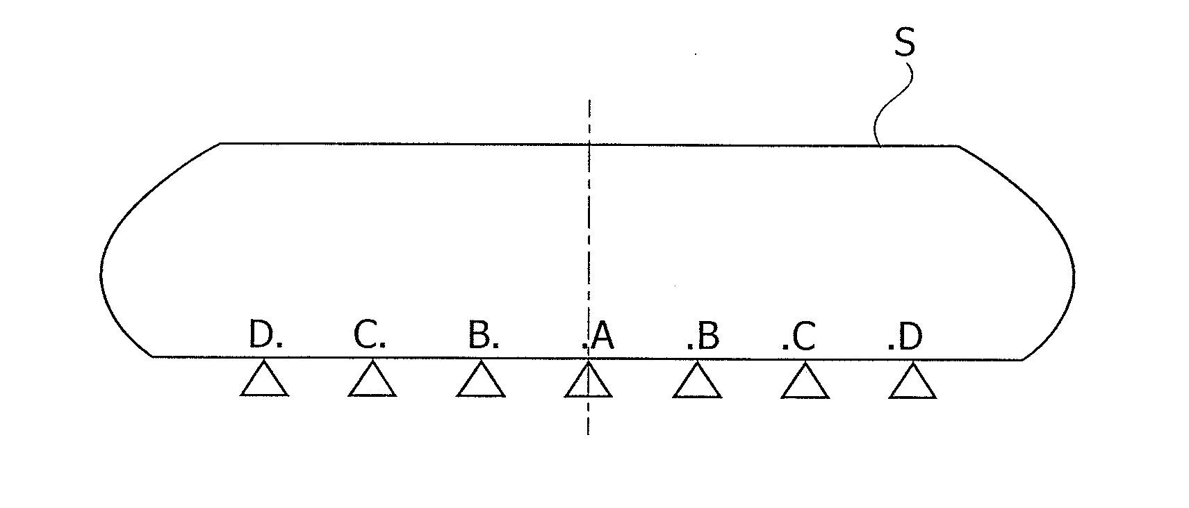
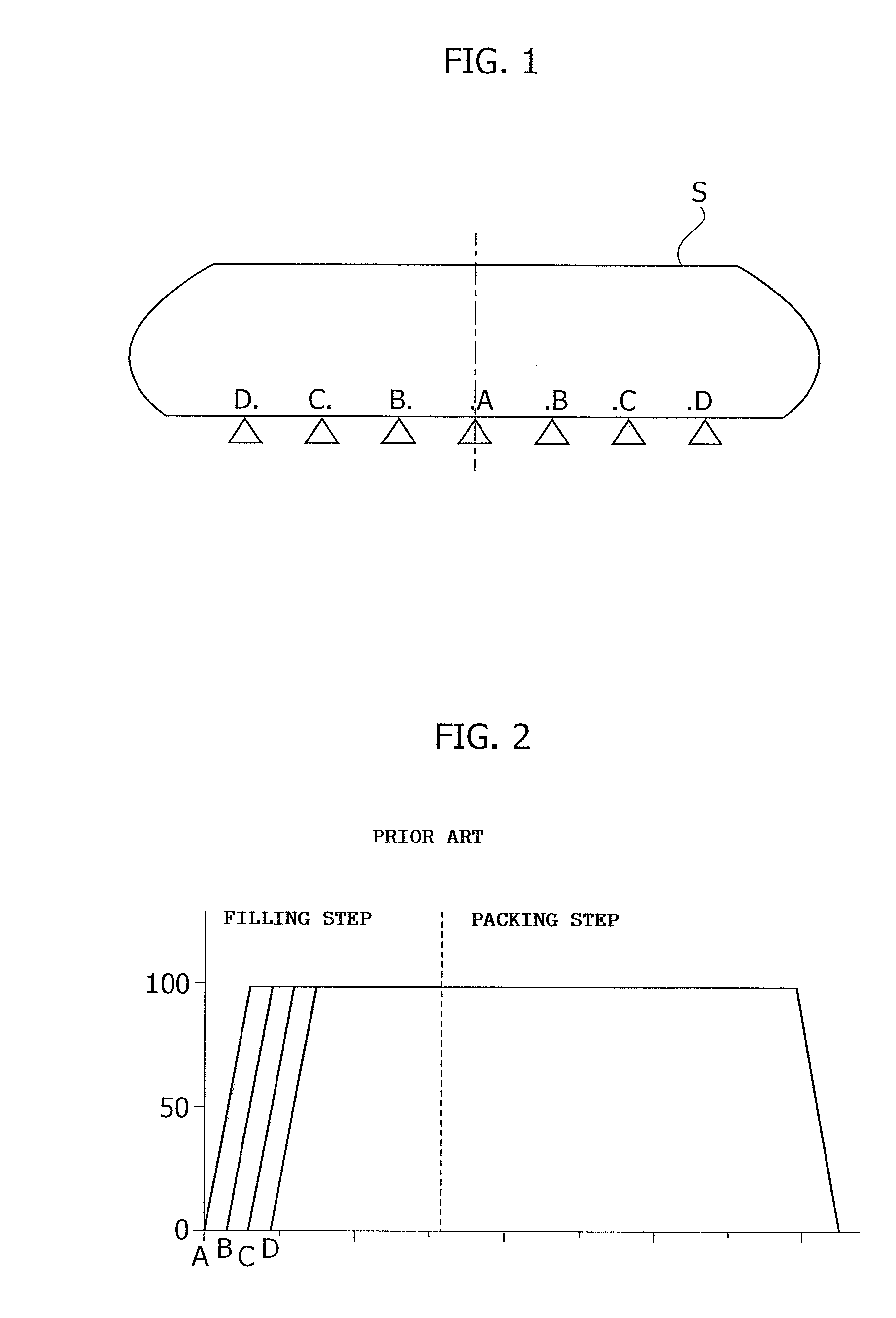
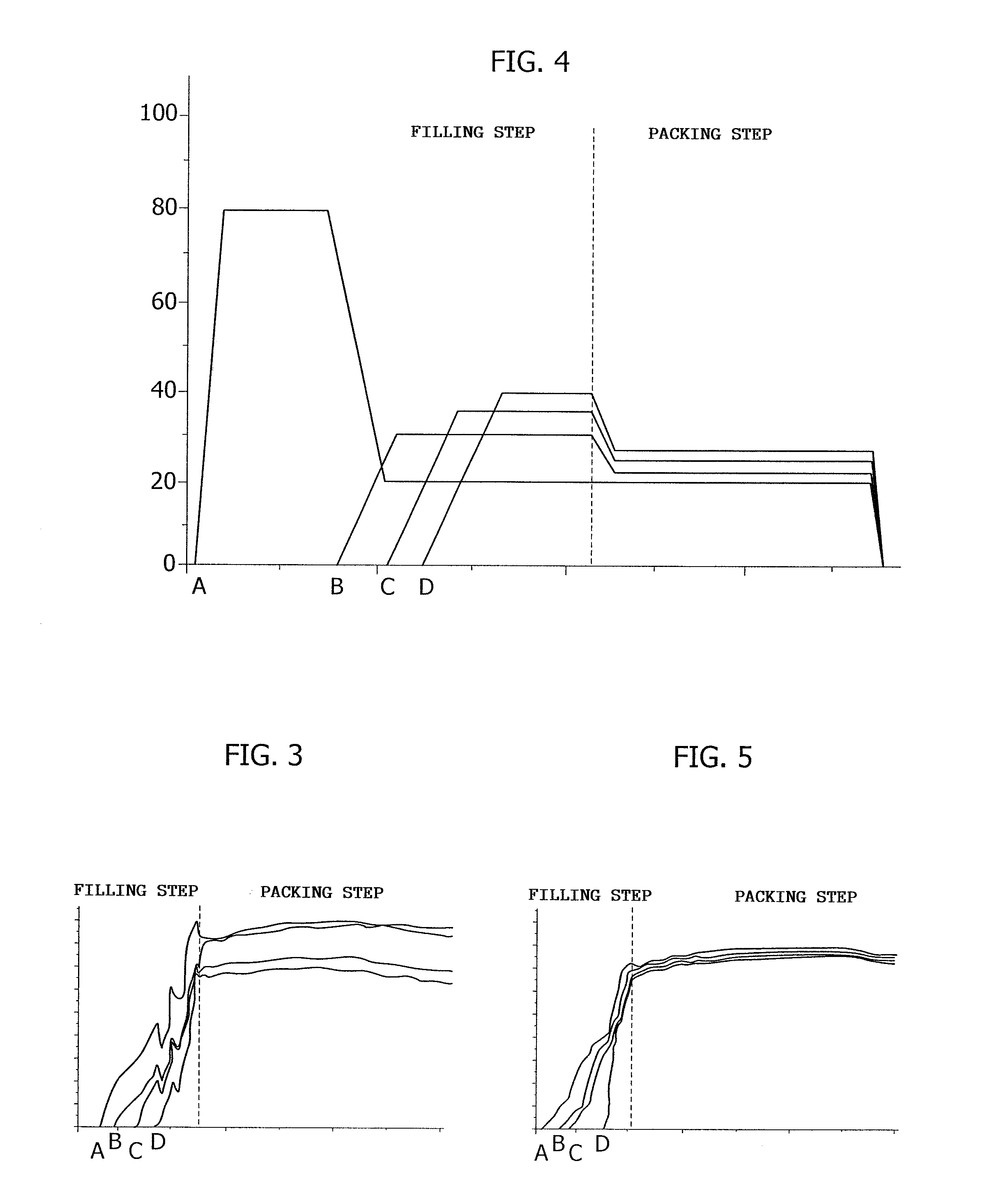
[0028]FIGS. 1, 2 and 3 have been previously described in the introduction, with reference to the sequential injection cycle implemented according to the prior art.

[0029]The chart of FIG. 4 represents the distinctive methods for opening the injectors A, B, C, D obtained through the sequential injection molding apparatus according to the invention. It should be observed that, as explained previously, each injector is provided with a respective shutter pin which can be moved axially between a complete closing position and a complete opening position through a respective electrical actuator, for example a rotary electric motor of the type described and illustrated in the previously mentioned EP-2679374A1. The electric motor is in turn actuated through an electronic control unit configured to operate according to the principles of the invention.

[0030]For each injector A, B, C, D, the chart of FIG. 4 represents, as a function of time, the position of the relative shutter pin, indicated as...


PUM

PropertyMeasurementUnit
Pressureaaaaaaaaaa

Abstract

A molding apparatus for the production of articles molded through sequential injection includes a mold having a cavity, a plurality of electrically actuated injectors arranged at central, intermediate and end positions, respectively, with respect to the mold cavity, and an electronic system for controlling the injectors for the actuation thereof according to a sequential cycle which provides for opening the central injector first, followed by the intermediate injectors and then the end injectors. The electronic control system is configured so that the opening sequential cycle occurs in such a way to obtain more linear and homogeneous pressure in the mold filling step, and lower packing pressure.

Description

FIELD OF THE INVENTION[0001]The present invention generally refers to the production of articles made of injection molded plastic material, and more particularly it regards a sequential injection molding apparatus.[0002]Apparatus thus made comprise a mold having a cavity, a plurality of injectors respectively arranged in central, intermediate and end positions with respect to the mold cavity and whose actuation occurs according to a sequential cycle which provides for opening the central injector first, followed by the intermediate injectors and then the end injectors. The injectors, of the shutter type, are formed by a nozzle within which a shutter pin, which controls the introduction of the plastic material coming from a distributor, can be axially moved in the mold cavity.[0003]In the injection molding industry substantial changes regarding the actuation of the shutter pin of each injector are currently in progress: as a matter of fact there is an ever increasing use of electrica...

Claims


Application Information

Patent Timeline
IPC IPC(8): B29C45/00B29C45/76
CPCB29C45/0025B29C2945/76648B29C2045/0032B29C45/762B29C45/13B29C45/77B29C2945/76545B29C2945/76498B29L2031/3044B29C45/281B29C45/0046B29C2945/76755B29C2945/76859B29C2945/76862B29C2045/2872
Inventor BAZZO, MAURIZIO
Owner INGLASS SPA
Learn More