Crankshaft

Active Publication Date: 2016-06-16
TOYOTA JIDOSHA KK
View PDF0 Cites 3 Cited by
  • Summary
  • Abstract
  • Description
  • Claims
  • Application Information

AI Technical Summary

Benefits of technology

The present invention provides a crankshaft that is both light and strong. This is achieved by using partial reinforcement on the crankshaft, which ensures rigidity without adding too much weight. This design helps improve fuel efficiency and reduces engine weight.

Problems solved by technology

Unfortunately, simply providing such reinforcement rather results in increase in weight of the crankshaft.
Increase in weight of the crankshaft causes increase in moment of inertia of the crankshaft, so that inconvenience, such as deterioration of fuel efficiency and increase in weight of an engine, is caused.

Method used


Image

  • Crankshaft
  • Crankshaft
  • Crankshaft

Examples


Embodiment Construction

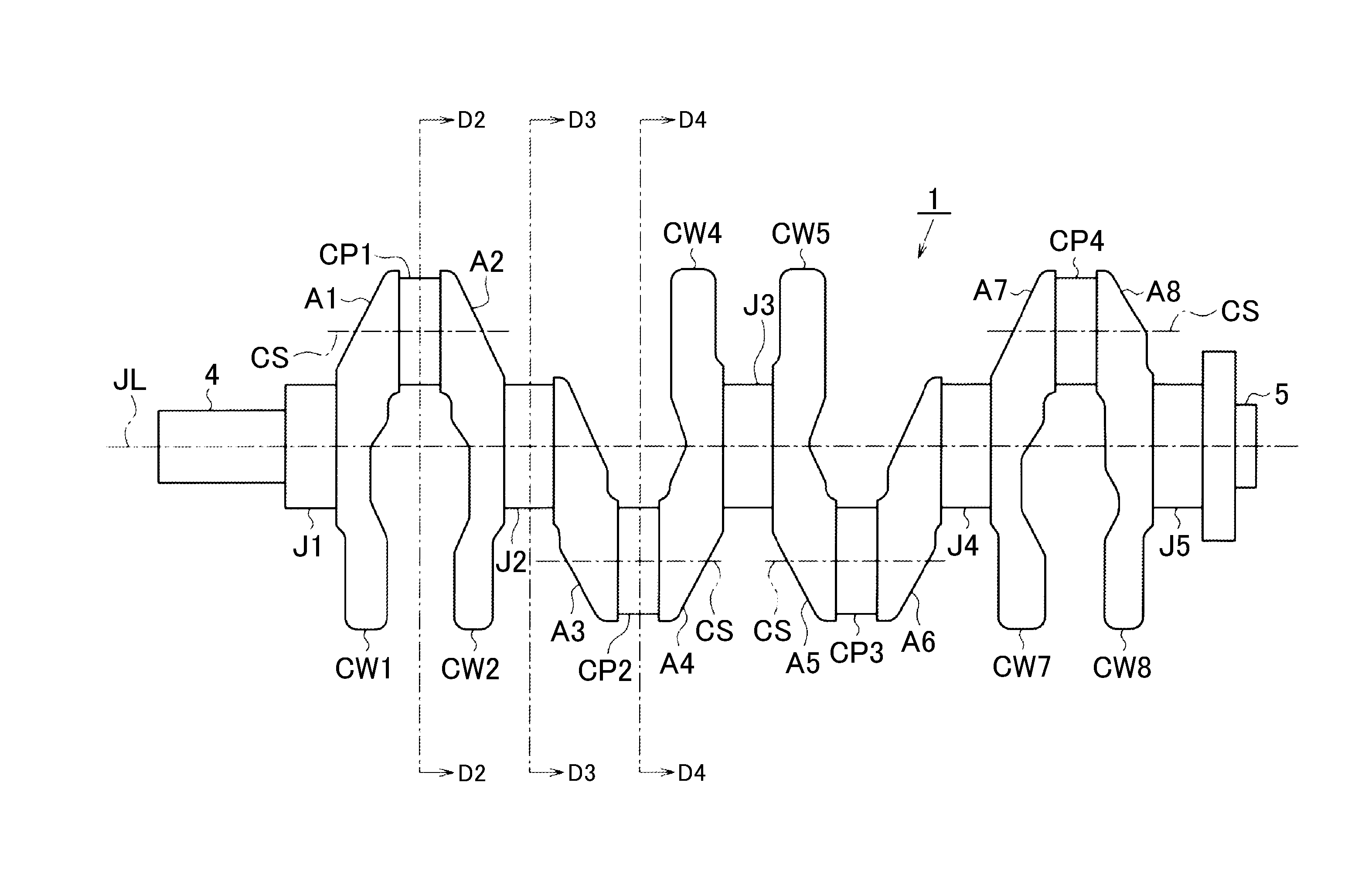
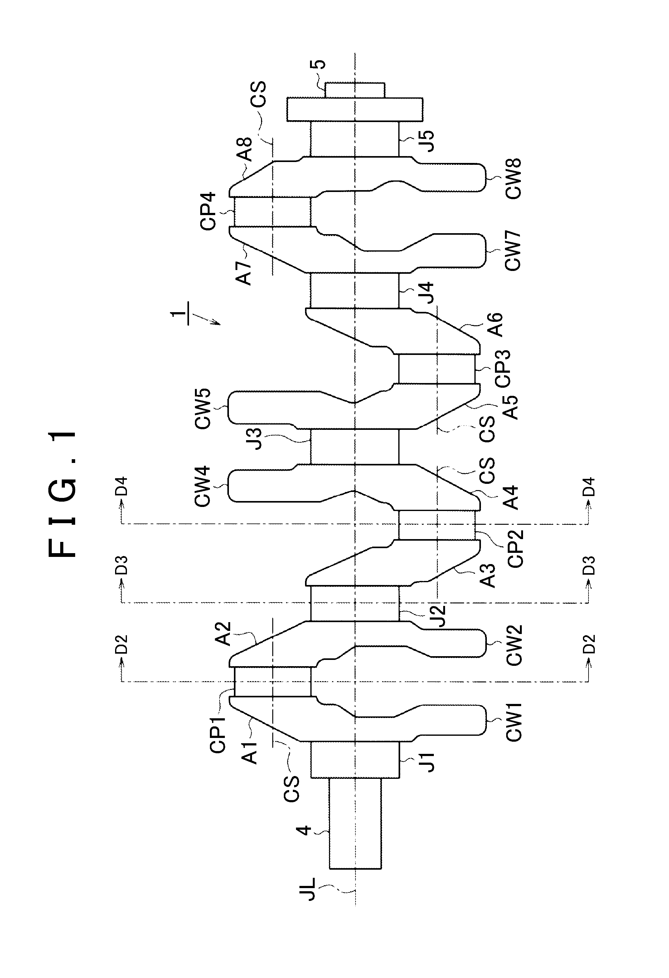
[0028]Hereinafter, one embodiment in which a crankshaft is embodied will be described with reference to FIG. 1 to FIG. 4. As shown in FIG. 1, a crankshaft 1 of the present embodiment is a flat plane crankshaft for an in-line four cylinder engine. The crankshaft is made of a manganese steel that is one of alloy steels for machine structure use, and is produced by forging.

[0029]A pulley or the like used for driving a timing belt or a fan belt is attached to a shaft end 4 of the crankshaft 1 on the left side of the drawing, for example. A flywheel averaging a shaft torque of an engine so as to attain smooth rotation is attached to a shaft end 5 of the crankshaft 1 on the right side of the drawing.

[0030]The crankshaft 1 is provided with five crank journals (hereinafter, referred to as journals) serving as a rotational center of the crankshaft 1. Hereinafter, a journal at a first position counted from the shaft end 4 is referred to as a first journal J1, a journal at a second position co...


PUM


Abstract

A flat plane crankshaft for an in-line four cylinder engine includes eight crank arms. A fourth crank arm and a fifth crank arm are respectively provided with counter weights. Each of a width of the fourth crank arm and a width of the fifth crank arm is configured to be smaller than a width of a second crank arm. Each of a width of the third crank arm and a width of the sixth crank arm is configured to be greater than the width of the second crank arm.

Description

INCORPORATION BY REFERENCE[0001]The disclosure of Japanese Patent Application No. 2014-252275 filed on Dec. 12, 2014 including the specification, drawings and abstract is incorporated herein by reference in its entirety.BACKGROUND OF THE INVENTION[0002]1. Field of the Invention[0003]The present invention relates to a crankshaft for an in-line four cylinder engine.[0004]2. Description of Related Art[0005]A crankshaft for an in-line four cylinder engine includes: crank journals serving as a rotational center of the crankshaft; crank pins disposed at positions eccentric to the corresponding crank journals, and to which connecting rods are coupled; and crank arms that couple the respective crank journals to the corresponding crank pins.[0006]Insufficient rigidity of crankshafts causes vibrations or the like during rotation thereof; therefore, partial reinforcement is often provided to the crankshafts so as to secure sufficient rigidity. An example of such partial reinforcement for secur...

Claims


Application Information

Patent Timeline
IPC IPC(8): F16F15/28
CPCF16F15/283F02B75/32F16C3/08F16C3/10F16C3/12F02B75/20F02B2075/1816F16C3/20F16C3/22F16C2360/22
Inventor ONO, KOICHI
Owner TOYOTA JIDOSHA KK
Why Eureka
Try Eureka