Rack and manufacturing method thereof

Inactive Publication Date: 2010-07-01
NSK LTD
View PDF16 Cites 21 Cited by
  • Summary
  • Abstract
  • Description
  • Claims
  • Application Information

AI Technical Summary

Benefits of technology

[0046]With the rack and rack manufacturing method of the present invention described above, it is possible to sufficiently secure the width dimension, strength and rigidity of the rack teeth, as well as it is possible to obtain a lightweight rack at low cost without increasing more than necessary the outer diameter of the portion where the rack teeth are not formed.
[0047]First, securing the width dimension of the rack teeth is accomplished by making the width of a portion where the rack teeth will be formed of part in the axial direction of the rod unit greater than the outer diameter of the remaining portion in the axial direction of the rod unit. Also, securing the strength and rigidity can be accomplished by making this rod unit from a solid material. In other words, the width dimension of the portion where the rack teeth will be formed of part in the axial direction of the rod unit is expanded while pressing to compress the material, and the radius of curvature of the portion that is separated in the circumferential direction from the portion where the rack teeth will be formed is made to be greater than the radius of curvature of the outer surface of the material. Therefore, it is possible to form rack teeth having a width dimension that is large in comparison with the outer diameter of the material. The portion where these rack teeth are formed differs from the rack teeth that are formed by pressing and expanding a hollow cylindrical tube shaped material as done in the conventional art disclosed in patent document 4 described above in that it is possible to secure sufficient thickness. It is possible to improve the strength and rigidity of the rack teeth portion by the amount that the width dimension is increased, and even further by the amount that the radius of curvature of the cross sectional shape of the portion that is separated in the circumferential direction from the portion where the rack teeth are formed is increased.
[0048]Moreover, obtaining a lightweight rack without increasing more than necessary the outer diameter of the portion where the teeth are not formed is accomplished by making the outer diameter of the remaining portion in the axial direction of the rod unit small even though the width dimension of the rack teeth is secured.
[0049]Furthermore, making a rack at low cost (keeping the production costs low) is accomplished by performing simple pre processing when forming the rack teeth by plastic working that prevents excess material from protruding outward in the radial direction and becoming burrs, which together with keeping the processing load to a minimum and making post processing to remove the excess material unnecessary. In other words, the width dimension of the portion of part in the axial direction of the rod unit where the rack teeth are to be formed is made to be greater than the outer diameter of the remaining portion in the axial direction by compressing the portion of the cross sectional shape that originally had the same cross sectional area as the remaining portion in the axial direction, and making the portion where the rack teeth are to be formed flat. In the state before the rack teeth are formed, the cross sectional area of part in the axial direction of the rod unit is nearly equal to the cross sectional area of the remaining portion in the axial

Problems solved by technology

When the rack of the steering-gear unit 5 described above is made by cutting work in which the material is cut to form the rack teeth, not only does the production cost increase, but it is also difficult to maintain the strength and rigidity of the rack teeth.
In the case of the conventional art that is disclosed in patent documents 1 and 2, the excess material is forced out from the side of the main portion of the rack, so the stress that occurs in the pair of dies that press the rack becomes high and it becomes difficult to maintain the life of the dies.
Moreover, a process for removing the excess material that is forced out from the side of the main portion in the shape of burrs is required, making it impossible to avoid increasing the production cost.
In either hot forging or warm forging, thermal expansion occurs due to the rise in temperature of the dies during processing, and since it is

Method used


Image

  • Rack and manufacturing method thereof
  • Rack and manufacturing method thereof
  • Rack and manufacturing method thereof

Examples


Example

First Embodiment

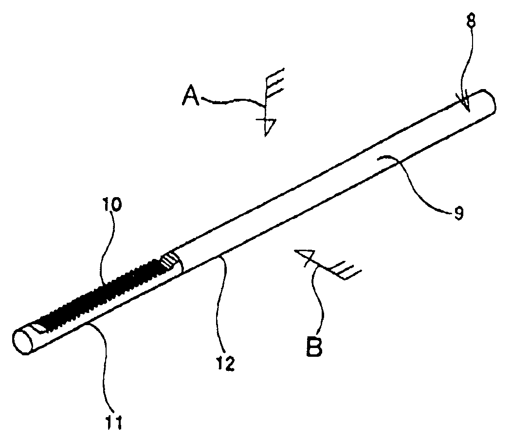
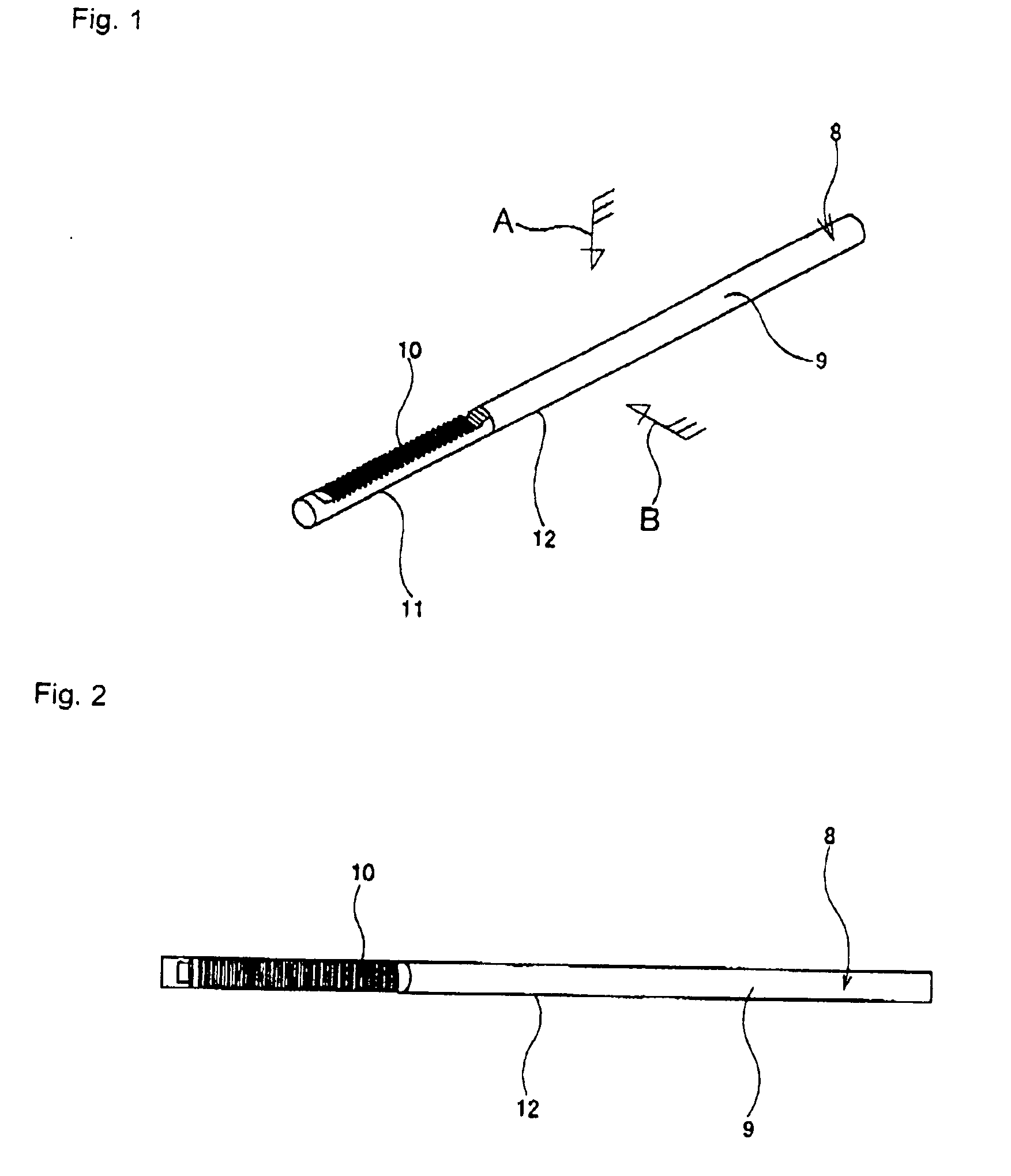
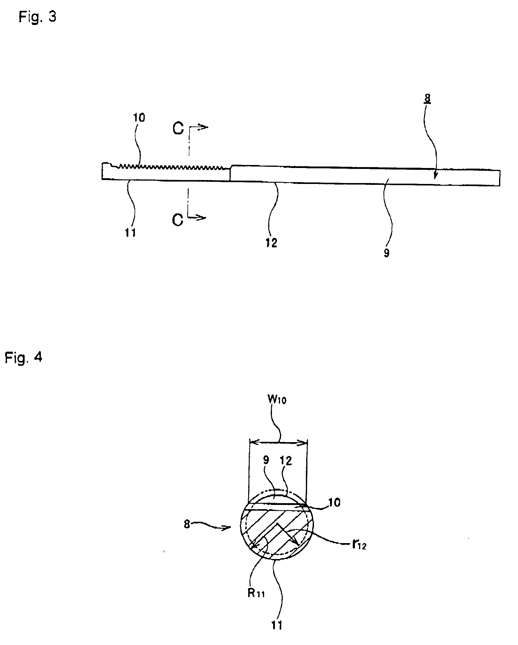
[0152]FIGS. 1 to 8 show a first embodiment of the present invention. First, the construction of the rack 8 of this embodiment will be explained based on FIGS. 1 to 4. In the explanation below, the radius of curvature of each surface, unless specified otherwise, is taken to be the radius of curvature of the cross sectional shape of each surface.

[0153]The rack 8 is made of a metal material such as carbon steel, stainless steel or the like, and comprises a rod unit 9 that is a solid material having a circular cross section, and rack teeth 10 that are formed by plastic working on one side surface in the radial direction of part in the axial direction (left part in FIGS. 1 to 3) of the rod unit 9. In this embodiment, the rod unit 9 is made from a single metal material that is the same over the entire length from the outer surface to the center. Moreover, in the part in the axial direction of this rod unit 9, the radius of curvature R11 (see FIG. 4) of the cross sectional ...

Example

[0165]FIG. 10 and FIG. 11 show a second embodiment of the present invention. In this embodiment, the amount of processing in the upsetting work shown in (A) to (B) of FIG. 10 is greater than that in the case of the first embodiment described above, and the width dimension of the intermediate material 20a that is obtained in this upsetting work is larger than in the case of the first embodiment. In addition, the radius of curvature of the partial cylindrical surface portion 17a is greater than in the case of the first embodiment.

[0166]In this embodiment, as shown in (C) to (D) of FIG. 10, the intermediate material 20a as described above, is pressed into a retaining hole 22 of a die 21 while plastically deforming both end portions in the width direction. This die 21 is the same as that used in the first embodiment. However, since the amount that the width dimension of the intermediate material 20a is larger, when pressing the intermediate material 20a into the retaining hole 22, both ...

Example

Third Embodiment

[0169]FIG. 12 shows a third embodiment of the present invention. In the case of this embodiment, as shown in (A) to (B) of FIG. 12, by performing an ironing work on a material 13 by passing it through a die 36, the outer diameter of this material 13 is reduced except for part in the axial direction. Moreover, the result is taken to be a preliminary intermediate material 37 having a portion in the axial direction whose outer diameter is greater than the outer diameter of the remaining portion in the axial direction, and of this preliminary intermediate material 37, the portion in the axial direction having the larger diameter is plastically deformed in the same manner as in the first embodiment or in the second embodiment described above to obtain a rack 8a as shown in (C) of FIG. 12. In the case of this kind of embodiment. it is possible to reduce the diameter of the portion of the rack 8a that is separated in the axial direction from the portion where the rack teeth...


PUM

PropertyMeasurementUnit
Lengthaaaaaaaaaa
Angleaaaaaaaaaa
Diameteraaaaaaaaaa

Abstract

To sufficiently secure the width dimension, strength and rigidity of the rack teeth 10, and to realize the light weight construction and the manufacturing method of the rack 8, the rack teeth 10 is formed by plastic working on one side surface in the radial direction of part in the axial direction of a rod unit 9 having a circular cross-sectional shape, and the curvature radius of the portion which is separated in the radial direction from the portion where the rack teeth 10 is formed, is made greater than that of the cross sectional shape of the outer surface of the axial remaining portion of the rod unit 9. For this purpose, as shown in (A) to (B), while a portion in the circumferential direction of part in the axial direction of a material 13 is compressed, the remaining portion in the circumferential direction of this part in the axial direction is formed into a partial cylindrical surface 17 whose curvature radius is larger than that of the outer surface of the material 13, to form an intermediate material 20. Then, as shown in (C) to (D), the rack teeth 10 are formed on the circumferential portion of the axial part of the intermediate material 20. At last, as shown in (E) to (F), sizing is performed to obtain the rack 8.

Description

FIELD OF THE INVENTION [0001]The present invention relates to the improvement of a manufacturing method for a rack that is installed in a rack and pinion steering apparatus as a steering apparatus for applying a steering angle to the steering wheels of an automobile, for example.BACKGROUND ART [0002]A rack and pinion steering apparatus, which uses a rack and pinion as a mechanism for converting rotational motion that is input from a steering wheel to linear motion for applying a steering angle, is widely used because it is made to be compact and lightweight, as well as has good rigidity and good feel of steering.[0003]FIG. 40 shows an example of this kind of rack and pinion steering apparatus. In this steering apparatus, the movement of a steering shaft 2 that is turned by the operation of a steering wheel 1 is transmitted to the input shaft 6 of a steering-gear unit 5 by way of a universal joint 3 and intermediate shaft 4. This steering-gear unit 5 comprises a pinion that is rotate...

Claims


Application Information

Patent Timeline
IPC IPC(8): F16H19/04B21D31/00
CPCB21K1/767F16H55/26B21J5/12Y10T29/49472Y10T29/49474Y10T29/49467Y10T74/1967
Inventor KOBAYASHI, KAZUTOMIZUSHIMA, YUKIHIROTA, KOTAROTSUBOUCHI, AKIRA
Owner NSK LTD
Why Eureka
Try Eureka