

Connecting rod for internal combustion engine and method of manufacturing the connecting rod
a technology of connecting rods and internal combustion engines, which is applied in the direction of connecting rods, metal-working devices, shafts and bearings, etc., can solve the problems of increasing reducing the positive effect of using, and the small end and the big end may not have sufficient rigidity, so as to reduce and reduce stress concentration. , the effect of reducing the weight of connecting rods
Inactive Publication Date: 2008-11-06
TOYOTA JIDOSHA KK
View PDF0 Cites 24 Cited by
- Summary
- Abstract
- Description
- Claims
- Application Information
AI Technical Summary
Benefits of technology
[0012]The present invention provides a technique that can secure sufficient rigidity and strength for respective portions of a connecting rod while achieving both a reduction in the weight of the connecting rod and suppression of stress concentration.
[0014]According to this arrangement, as compared with a connecting rod in which the column member, the small end member, and the big end member are mechanically connected together, the bonding portions of the connecting rod constituent members are integrated together by diffusion bonding with their microstructures (metallographic structures) fused together, thereby making it possible to reduce the degree of stress concentration at respective portions of the connecting rod. This eliminates the need to increase the thickness to achieve stress dispersion. Therefore, sufficient strength and rigidity can be secured for respective portions without increasing the weight of the connecting rod, thereby making it possible to sufficiently satisfy performance requirements placed on the connecting rod, such as high strength, high rigidity, and light weight.
[0017]Further, the constituent materials of the small end member, column member, and big end member may be different from each other. According to this arrangement, the degree of stress concentration at the bonding portion between the small end member and the column member and at the bonding portion between the big end member and the column member can be reduced. Therefore, in this case well, there is no need to increase the thickness to achieve stress dispersion. As a result, sufficient strength and rigidity can be secured for respective portions without increasing the weight of the connecting rod, thereby making it possible to sufficiently satisfy performance requirements placed on the connecting rod, such as high strength, high rigidity, and light weight.
[0021]According to this arrangement, high rigidity is secured for the small end and the big end, thereby making it possible to prevent a gap from being produced between the small end and the piston pin, and between the big end and the crankpin. Generation of impact noise due to the collision of these members is thus effectively avoided, thereby reducing noise and vibration of the engine. Further, because high rigidity is secured for the column portion, the column portion effectively transmits the explosive force of an air-fuel mixture to the crankshaft, and can sufficiently withstand the above-mentioned explosive force that intermittently acts on the column portion, thereby making it possible to improve the durability of the connecting rod.
[0026]According to the present invention, a plurality of connecting rod constituent members (for example, the small end member, the big end member, and the column member) as separate members are made of different kinds of metal, and these members are bonded by diffusion bonding. It is thus possible to reduce the degree of stress concentration that would occur when mechanically connecting these members as mentioned above, and hence there is no need to increase the thickness to achieve stress dispersion. Therefore, sufficient strength and rigidity can be secured for respective portions without increasing the weight of the connecting rod, thereby making it possible to provide a connecting rod that can sufficiently satisfy such requirements as high strength, high rigidity, and light weight.
Problems solved by technology
However, this leads to an increase in the weight of the connecting rod, which reduces the positive effect of using the above-mentioned lightweight alloy.
Further, in the case of the configuration described in JP-A-Sho 63-199916 mentioned above, the small end and the big end may not have sufficient rigidity.
In this case, a gap is produced between the small end and the piston pin and between the big end and the crankpin, and thus collision occurs between these members, generating so-called impact sound.
This presents a major obstacle to reducing noise and vibration of an engine.
Method used
View moreImage
Smart ImageViewing Examples

Examples
example 1
[0047]The end constituent material is TiB2, and the column-portion constituent material is steel containing vanadium.
example 2
[0048]The end constituent material is steel, and the column-portion constituent material is titanium alloy.
example 3
[0049]The end constituent material is steel containing titanium alloy, and the column-portion constituent material is titanium alloy.
Login to View More PUM
| Property | Measurement | Unit |
|---|---|---|
| rigidity | aaaaa | aaaaa |
| strength | aaaaa | aaaaa |
| shape | aaaaa | aaaaa |
Abstract
A small end member constituting a small end, a column member constituting a column portion, and a big end member constituting a big end of a connecting rod are formed as separate members. In addition, the small end member and the big end member are each made of a high-rigidity material, and the column member is made of a high-strength material. These members are integrally bonded by liquid phase diffusion bonding, thus providing a connecting rod that can achieve suppression of stress concentration.
Description
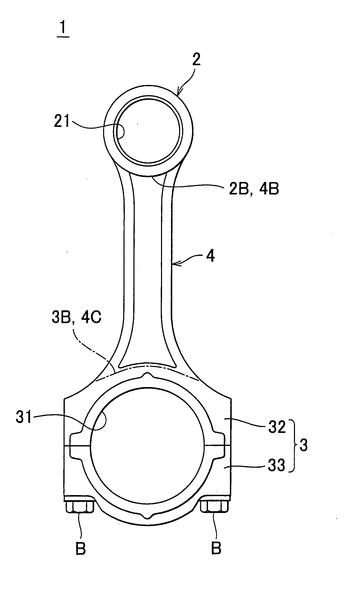
INCORPORATION BY REFERENCE[0001]The disclosure of Japanese Patent Application No. 2006-278394 filed on Oct. 12, 2006, including the specification, drawings and abstract is incorporated herein by reference in its entirety.BACKGROUND OF THE INVENTION[0002]1. Field of Invention[0003]The present invention relates to a connecting rod employed in an internal combustion engine, such as an automobile engine, and more specifically to a connecting rod formed by a composite of different kinds of material, and a method of manufacturing the connecting rod.[0004]2. Description of Related Art[0005]As described in Japanese patent application publication Nos. JP-A-2000-179535 and JP-A-2001-18056, in an internal combustion engine such as an automobile engine, a piston and a crankshaft are connected to each other by a connecting rod, and the explosive force of an air-fuel mixture during the combustion stroke is transmitted to the crankshaft via the piston and the connecting rod.[0006]As shown in FIG. ...
Claims
Login to View More Application Information
Patent Timeline
 Patent Type & AuthorityApplications(United States)
IPC IPC(8): F16C7/00B21D53/84
CPCF16C7/023Y10T29/4929Y10T74/2162
InventorYASUHARA, JUNICHIHAYAMA, KENJI
OwnerTOYOTA JIDOSHA KK