Wire harness manufacturing method

Active Publication Date: 2017-08-10
YAZAKI CORP
View PDF3 Cites 0 Cited by
  • Summary
  • Abstract
  • Description
  • Claims
  • Application Information

AI Technical Summary

Benefits of technology

[0020]According to one or more embodiments, since the vibration suppressing part having a reinforcing rib is formed, even when the exterior member receives an external force, it can be made difficult to be bent or broken easily. That is, the lowered rigidity of the exterior member can be prevented.
[0021]According to one or more embodiments, since there is employed the method which, after inserting the conduction path into the exterior member, forms the vibration suppressing part having a convex shape on the inside of the exterior member, there is provided an effect that, while paying attention to the workability of insertion of the conduction path, the vibration of the conduction path within the exterior member can be suppressed. Also, according to this invention, there is also p

Problems solved by technology

In the above conventional art, when the conduction paths within the exterior member are caused to vibrate due to the vibrations of the automobile while running, the coating of the conduction paths (in the case that the coating has a shield function, a braided wire or a metal foil existing on the outside of the conduction path) can be strongly butted against the tube inner surface of the exterior member into damage.
However, to reduce the inside diameter of the exterior

Method used


Image

  • Wire harness manufacturing method
  • Wire harness manufacturing method
  • Wire harness manufacturing method

Examples


Example

Embodiment 1

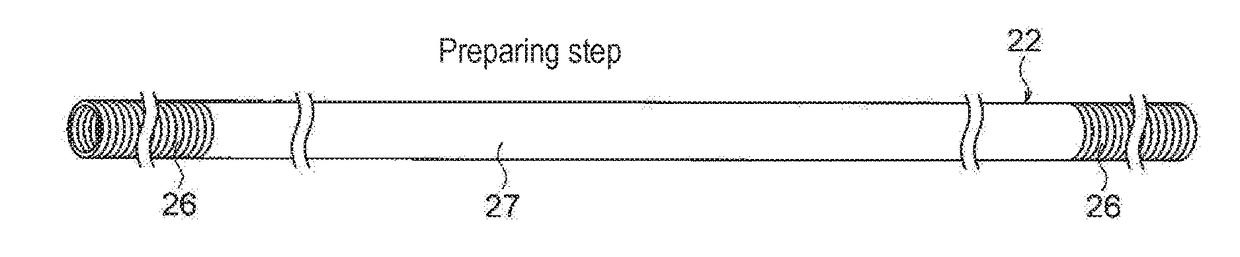
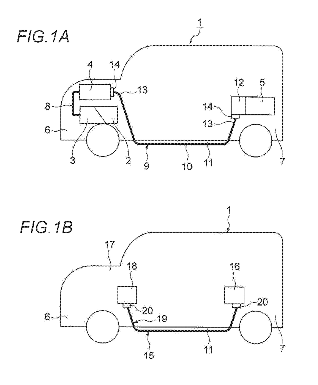
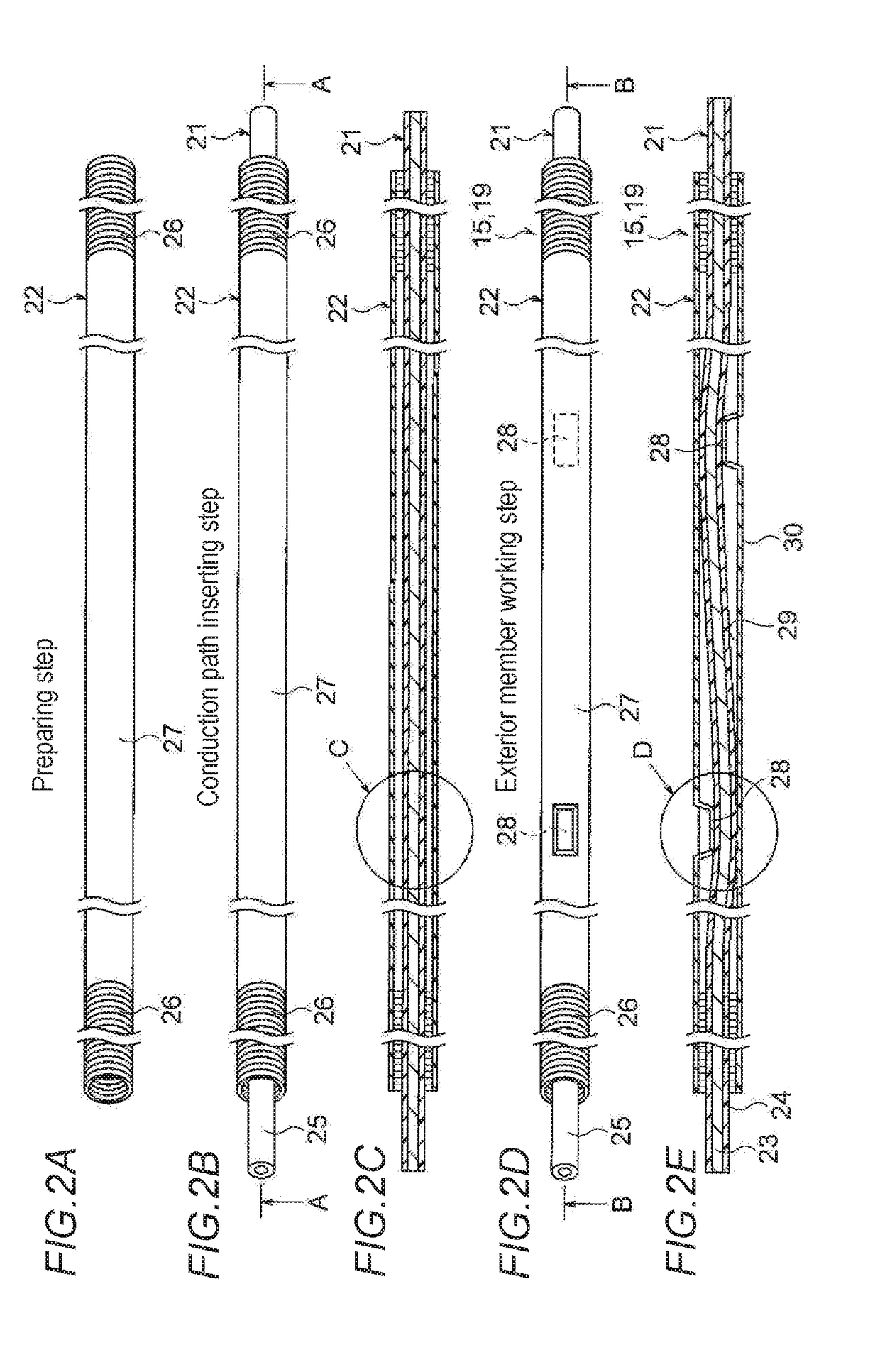
[0031]Description is given below of an embodiment 1 with reference to the drawings. FIGS. 1A and 1B show a wire harness manufactured by a manufacturing method according to the invention: specifically, FIG. 1A is a schematic view of the arranged state of a high voltage wire harness; and, FIG. 1B is a schematic view of the arranged state of a low voltage wire harness different from one of FIG. 1A. FIGS. 2A to 2E, and 3A and 3B are explanatory views of a wire harness manufacturing method according to the invention: specifically, FIG. 2A is a perspective view of an exterior member, FIG. 2B is a view of a conduction path inserting step, FIG. 2C is a section view taken along the A-A arrow line of FIG. 2B, FIG. 2D is a view of an exterior member working step, and FIG. 2E is a section view taken along the B-B arrow line of FIG. 2D; and, FIG. 3A is a partially enlarged view of the C part of FIG. 2C, and FIG. 3B is a partially enlarged view of the D part of FIG. 2E.

[0032]In this e...

Example

Embodiment 2

[0073]Description is given below of an embodiment 2 with reference to the drawings. FIGS. 4A and 4B are views of a second embodiment of a wire harness manufactured according to the manufacturing method of the invention. That is, FIG. 4A is a perspective view of the structure of the wire harness, and FIG. 4B is a section view taken along the E-E arrow line of FIG. 4A. Here, the composing members of this embodiment, which are basically the same as those of the embodiment 1, are given the same designations and thus the detailed description thereof is omitted.

[0074]15>

[0075]In FIGS. 4A and 4B, a harness main body 19 constituting a long wire harness 15 includes two conduction paths 21 and an exterior member 22 for storing and protecting the two conduction paths 21. In the exterior member 22, there are formed multiple vibration suppressing parts 28 which are the characteristic part of the invention (they are formed in the same method as the embodiment 1). The vibration suppres...

Example

Embodiment 3

[0078]Description is given below of an embodiment 3 with reference to the drawings. FIGS. 5A and 5B show a wire harness according to a third embodiment manufactured by the manufacturing method of the invention. That is, FIG. 5A is a perspective view of the structure of the wire harness and FIG. 5B is a section view taken along the F-F arrow line of FIG. 5A. Here, the composing members of this embodiment, which are basically the same as those of the embodiment 1, are given the same designations and thus the detailed description thereof is omitted.

[0079]15>

[0080]In FIGS. 5A and 5B, a harness main body 19 constituting a long wire harness 15 includes a conduction path 21 and an exterior member 22 for storing and protecting the conduction path 21. The exterior member 22 includes multiple vibration suppressing parts 28 (which are formed in the same method as the embodiment 1) that provide the characteristic part of the invention. The vibration suppressing parts 28 of the embod...


PUM


Abstract

A wire harness manufacturing method includes a conduction path inserting step of inserting one or a plurality of conduction paths from one end of a resin-made tubular exterior member to the other end thereof, and an exterior member working step of performing post-working on one or a plurality of parts of the exterior member, after the conduction path inserting step. The exterior member working step includes forming a convex-shaped part when viewed from an inner surface side of the exterior member by performing the post-working using heat on an outer surface side of the exterior member. The convex-shaped part is a vibration suppressing part to reduce a play rate of the conduction path in the exterior member and suppress a vibration of the conduction path.

Description

CROSS REFERENCE TO RELATED APPLICATIONS[0001]This application claims priority from Japanese Patent Application No. 2016-020409 filed on Feb. 5, 2016, the entire contents of which are incorporated herein by reference.BACKGROUND OF THE INVENTION[0002]Field of the Invention[0003]The invention relates to a method for manufacturing a wire harness including a resin-made tubular exterior member and one or multiple conduction paths to be inserted into and protected by the exterior member.[0004]Description of Related Art[0005]In order to electrically connect apparatuses mounted on an automobile to each other, there is used a wire harness. The wire harness includes a tubular exterior member and one or multiple conduction paths to be stored in the exterior member. For example, a wire harness disclosed in the below-cited patent document 1 is arranged to pass through the vehicle under-floor of an automobile. The part of the wire harness corresponding to the vehicle under-floor is arranged straig...

Claims


Application Information

Patent Timeline
IPC IPC(8): H01B13/012
CPCH01B13/012B60R16/0215H01B13/01263H01B13/24H02G3/0462
Inventor INAO, SHINICHIADACHI, HIDEOMIYANAZAWA, KENTA
Owner YAZAKI CORP
Why Eureka
Try Eureka