Annular spring and robot joint mechanism using the same

Active Publication Date: 2016-04-21
HONDA MOTOR CO LTD
View PDF4 Cites 5 Cited by
  • Summary
  • Abstract
  • Description
  • Claims
  • Application Information

AI Technical Summary

Benefits of technology

The invention is a new design for a robot joint mechanism. Compared to conventional designs, it is smaller and lighter, and can absorb impacts easier. This means it can be used in smaller and lighter robots.

Problems solved by technology

Therefore, in order to assure sufficiently low rigidity as well as a sufficiently large amount of displacement in the relative rotational direction of the outer and inner peripheral members for absorbing the impact, it is necessary to increase the axial length and / or the radius, making it difficult to reduce the size and / or weight.
This means that in the robot joint mechanism using the conventional annular spring, it is necessary to secure a space for disposing the bearing therein, also making it difficult to reduce the size and / or weight.

Method used


Image

  • Annular spring and robot joint mechanism using the same
  • Annular spring and robot joint mechanism using the same
  • Annular spring and robot joint mechanism using the same

Examples


first embodiment

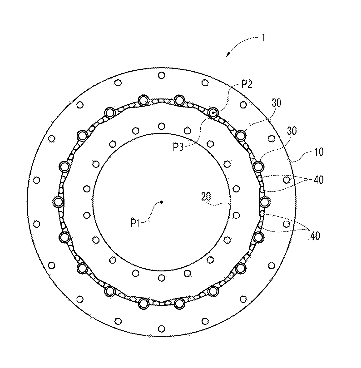
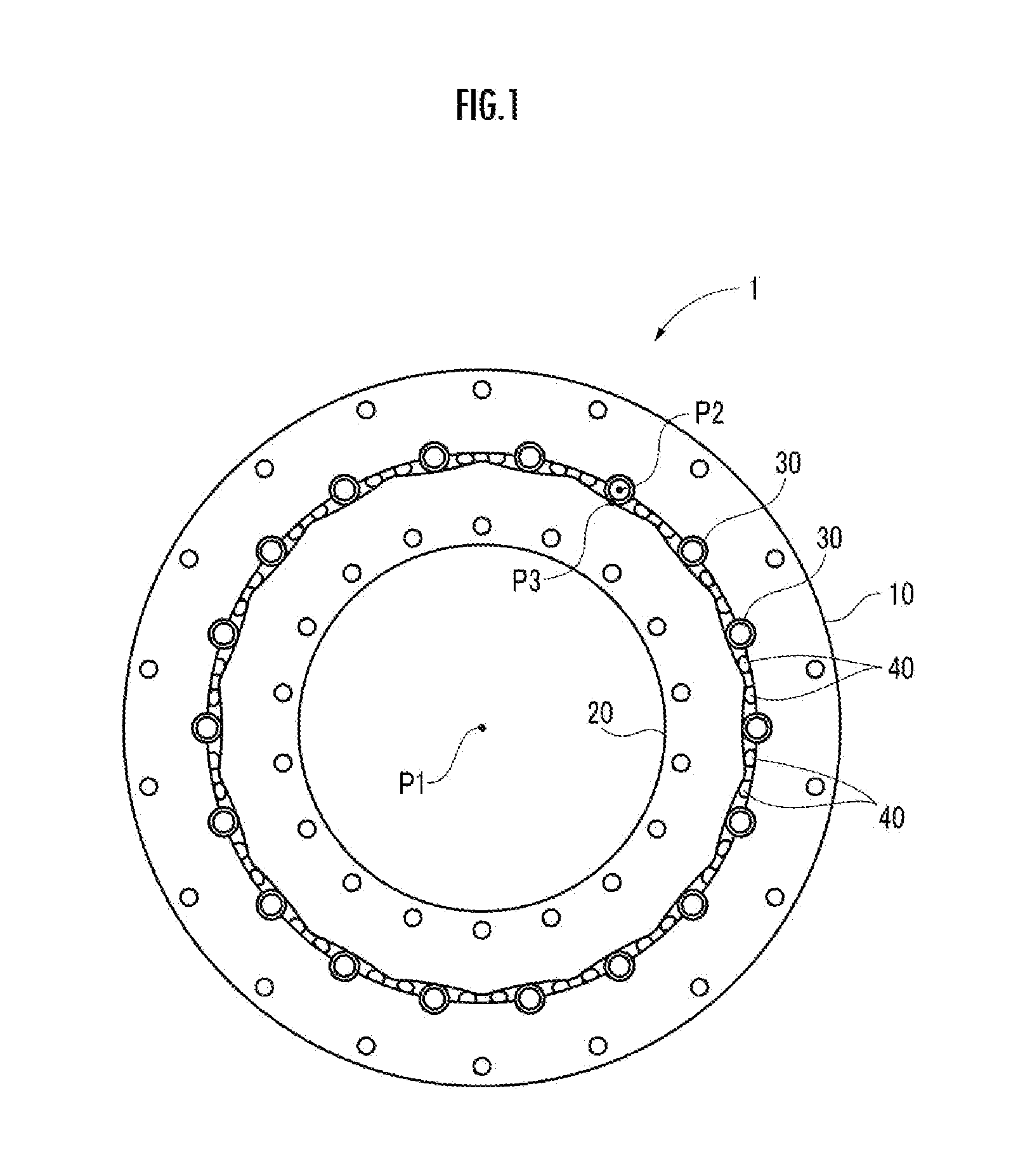
[0033]First, the configuration of an annular spring 1 according to a first embodiment will be described with reference to FIGS. 1 to 3.

[0034]As shown in FIG. 1, the annular spring 1 of the present embodiment includes an annular outer peripheral member 10, an annular inner peripheral member 20 arranged on an inner peripheral side of the outer peripheral member 10 concentrically with and rotatable relatively to the outer peripheral member 10, a plurality of pipe springs 30 (elastic members) arranged between the outer peripheral member 10 and the inner peripheral member 20, and a cross roller bearing 40 arranged between the outer peripheral member 10 and the inner peripheral member 20, and between the pipe springs 30.

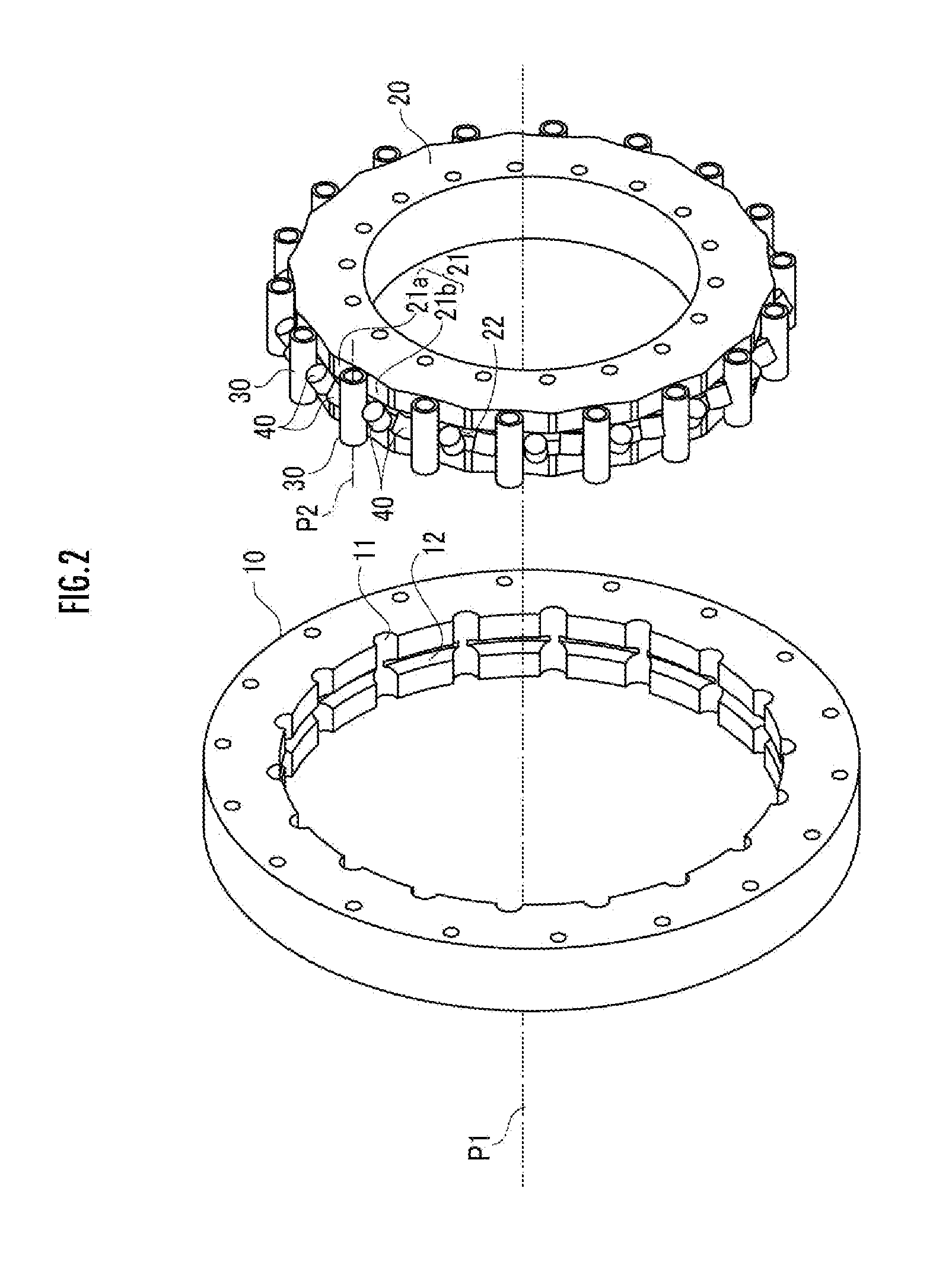
[0035]As shown in FIG. 2, on an inner peripheral surface of the outer peripheral member 10, a plurality of recesses 11, into which the pipe springs 30 are rotatably fitted, and an outer peripheral side bearing groove 12 are formed. The outer peripheral member 10 has a cent...

second embodiment

[0065]A robot joint mechanism using the annular spring of the first embodiment will now be described as a second embodiment of the present invention. The robot joint mechanism of the present embodiment is used, for example, for the robot as follows.

[0066]As shown in FIG. 5, the robot R includes, similarly to a human being, a body 51 corresponding to a torso, a head 52 disposed on top of the body 51, right and left arms 53 extended from respective sides of the upper portion of the body 51, a hand 54 provided at the tip end of each arm 53, right and left legs 55 extended downward from the lower portion of the body 51, and a foot 56 attached to the tip end of each leg 55.

[0067]The robot R is configured to be able to bend and stretch the arms and legs at joint mechanisms which correspond to the human shoulder joints, elbow joints, wrist joints, hip joints, knee joints, and ankle joints.

[0068]As shown in FIG. 6, the joint mechanism built in an arm 53 of the robot R includes: a base link ...


PUM


Abstract

On an inner peripheral surface of an outer peripheral member 10, a recess 11 is formed to which a pipe spring 30 is fitted. On an outer peripheral surface of an inner peripheral member 20 arranged concentrically with and rotatable relatively to the outer peripheral member 10 on an inner peripheral side of the outer peripheral member 10, a cam surface 21 is formed which abuts against the pipe spring 30. The cam surface 21 protrudes in the radial direction as it is farther away in the circumferential direction of the outer peripheral member 10 from the point of contact with the pipe spring 30 in the state where no load is applied.

Description

BACKGROUND OF THE INVENTION[0001]1. Field of the Invention[0002]The present invention relates to an annular spring which transmits a rotary driving force transmitted to one of an inner peripheral member and an outer peripheral member to the other, and a robot joint mechanism using the same.[0003]2. Description of the Related Art[0004]There is conventionally known a robot which includes, similarly to a human being, a body corresponding to a torso, a head disposed on top of the body, right and left arms extended from respective sides of the upper portion of the body, a hand provided at the tip end of each arm, right and left legs extended downward from the lower portion of the body, and a foot attached to the tip end of each leg. This kind of robot is capable of bending and stretching the arms and legs at joint mechanisms corresponding to the human shoulder joints, elbow joints, wrist joints, hip joints, knee joints, and ankle joints or the like.[0005]As the joint mechanism, there is ...

Claims


Application Information

Patent Timeline
IPC IPC(8): B25J19/00F16D3/12B25J9/10F16D3/64
CPCB25J19/0091F16D3/64Y10S901/49B25J9/1025Y10S901/25F16D3/12
Inventor MIYAZAKI, SUSUMU
Owner HONDA MOTOR CO LTD
Why Eureka
Try Eureka