Damper device

Active Publication Date: 2016-12-08
AISIN AW CO LTD
View PDF0 Cites 11 Cited by
  • Summary
  • Abstract
  • Description
  • Claims
  • Application Information

AI Technical Summary

Benefits of technology

[0010]In the damper device, the dynamic damper which includes the mass body and the vibration absorption elastic body which is disposed between the mass body and the first rotary element which is one of the plurality of rotary elements is coupled to the first rotary element. In addition, the second rotary element which is one of the plurality of rotary elements to which the dynamic damper is not coupled has the additional coupling portion which is configured to be coupled to an end portion of the vibration absorption elastic body before relative rotation between the input element and the output element is restricted by the rotation restriction stopper. The damper device further has the elastic body stopper which restricts torsion of one of the first and second elastic bodies before relative rotation between the input element and the output element is restricted by the rotation restriction stopper and at least by the time when the additional coupling portion is coupled to th

Problems solved by technology

However, incorporating the dynamic damper with the damper device does not it

Method used


Image

  • Damper device
  • Damper device
  • Damper device

Examples


Example

[0026]Now, an embodiment of the present disclosure will be described with reference to the drawings.

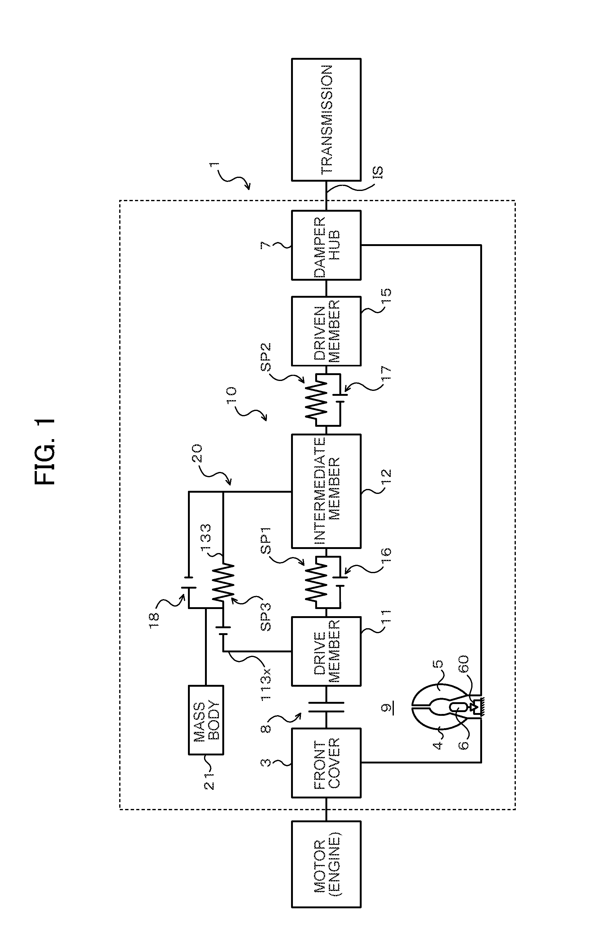
[0027]FIG. 1 is a schematic configuration diagram illustrating a starting device 1 that includes a damper device 10 according to an embodiment of the present disclosure. The starting device 1 illustrated in the drawing is mounted on a vehicle that includes an engine (internal combustion engine) that serves as a motor. In addition to the damper device 10, the starting device 1 includes: a front cover 3 that serves as an input member coupled to a crankshaft of the engine; a pump impeller (input-side fluid transmission element) 4 fixed to the front cover 3; a turbine runner (output-side fluid transmission element) 5 that is coaxially rotatable with the pump impeller 4; a damper hub 7 that serves as an output member coupled to the damper device 10 and fixed to an input shaft IS of a transmission that is an automatic transmission (AT) or a continuously variable transmission (CVT); a lock-u...


PUM


Abstract

A dynamic damper is coupled to an intermediate member of a damper device. A drive member of the damper device has additional abutment portions coupled to end portions of vibration absorption springs of the dynamic damper before both first and second inter-element stoppers operate. The second inter-element stoppers operate before the first inter-element stoppers operate and at least by the time when the additional coupling portions are coupled to end portions of the vibration absorption springs. Outer springs and the vibration absorption springs act in parallel to transfer torque after the additional coupling portions are coupled to end portions of the vibration absorption springs.

Description

CROSS REFERENCE TO RELATED APPLICATIONS[0001]This application is a National Stage of International Application No. PCT / JP2015 / 055938 filed Feb. 27, 2015, claiming priority based on Japanese Patent Application Nos. 2014-039655 filed Feb. 28, 2014 and 2014-129301 filed Jun. 24, 2014, the contents of all of which are incorporated herein by reference in their entirety.TECHNICAL FIELD[0002]The present disclosure relates to a damper device that has a plurality of rotary elements that include at least an input element and an output element, a torque transfer elastic body that transfers torque between the plurality of rotary elements, and a dynamic damper coupled to one of the plurality of rotary elements.BACKGROUND ART[0003]There has hitherto been known a damper device that includes a first elastic body that transfers torque between an input element and an output element, a second elastic body disposed on the inner side of the first elastic body to transfer torque between the input element...

Claims


Application Information

Patent Timeline
IPC IPC(8): F16F15/123F16F15/14
CPCF16F15/1428F16F15/12366Y10T74/2131
Inventor ITO, KAZUYOSHIARAKI, KEIZOHIRAI, YUICHIROWAJIMA, MASAKIUENO, MAKOTOKANYAMA, YUJITSUDA, KOTARO
Owner AISIN AW CO LTD
Why Eureka
Try Eureka