Lighting device and luminaire

Active Publication Date: 2016-06-16
SIGNIFY HLDG BV
View PDF1 Cites 8 Cited by
  • Summary
  • Abstract
  • Description
  • Claims
  • Application Information

AI Technical Summary

Benefits of technology

This patent describes a lighting device that effectively cools its components while mounted in a luminaire. This is achieved by placing a fan in a slanted position, which maximizes the space usage and reduces noise levels. The fan is positioned between the air inlet and a plurality of fins in the conduit, which increases the surface area of the heat sink and remains thermally decoupled from the fan. The lighting device includes a driver circuit and a separate heat sink for cooling the driver circuit, ensuring efficient cooling without overheating the fan. This feature improves the customer satisfaction of the luminaire and prevents failure of the lighting device due to restricted air flow.

Problems solved by technology

However, there are still difficulties to overcome in order to improve customer satisfaction and increase market penetration.
For instance, SSL-based devices are often perceived to create light that is less aesthetically pleasing compared to traditional alternatives.
Also, variations in the light produced by SSL-based lighting devices can be unsatisfactory.
Such variations for instance can occur when the thermal management of the SSL elements of the device is insufficient, such that the operating temperature of the SSL elements may vary, which can alter the colour point produced by the SSL elements, as the colour point typically is a function of the operating temperature of the SSL elements.
Such thermal management challenges are particularly prevalent when designing high-power SSL-based lighting devices, e.g. high-power LED lamps.
Quite often the scaling up of the heat sink for dissipating the heat generated by the one or more SSL elements is either insufficient or practically impossible due to the restricted volumes in which the heat sink needs to be placed, e.g. inside the inner volume of a standard size light bulb.
However, the placement of such a fan in the direct vicinity of the LED elements (or other SSL elements) is not without problems.
The heat generated by the SSL elements can reduce the lifetime of the fan and the lighting device as a whole.
In order to avoid this, the capacity of the fan may be increased, but this typically also increases the noise levels of the fan, which may be unacceptable from a consumer satisfaction point of view.
Moreover, the position of the air inlets and outlets in this LED light source is far from ideal, especially when the light source is to be mounted in a closed luminaire, where the close vicinity of the walls of the luminaire to the air inlet and outlets may severely restrict the air flow, which can lead to insufficient cooling of the light source.

Method used


Image

  • Lighting device and luminaire
  • Lighting device and luminaire
  • Lighting device and luminaire

Examples


Embodiment Construction

[0040]It should be understood that the Figures are merely schematic and are not drawn to scale. It should also be understood that the same reference numerals are used throughout the Figures to indicate the same or similar parts.

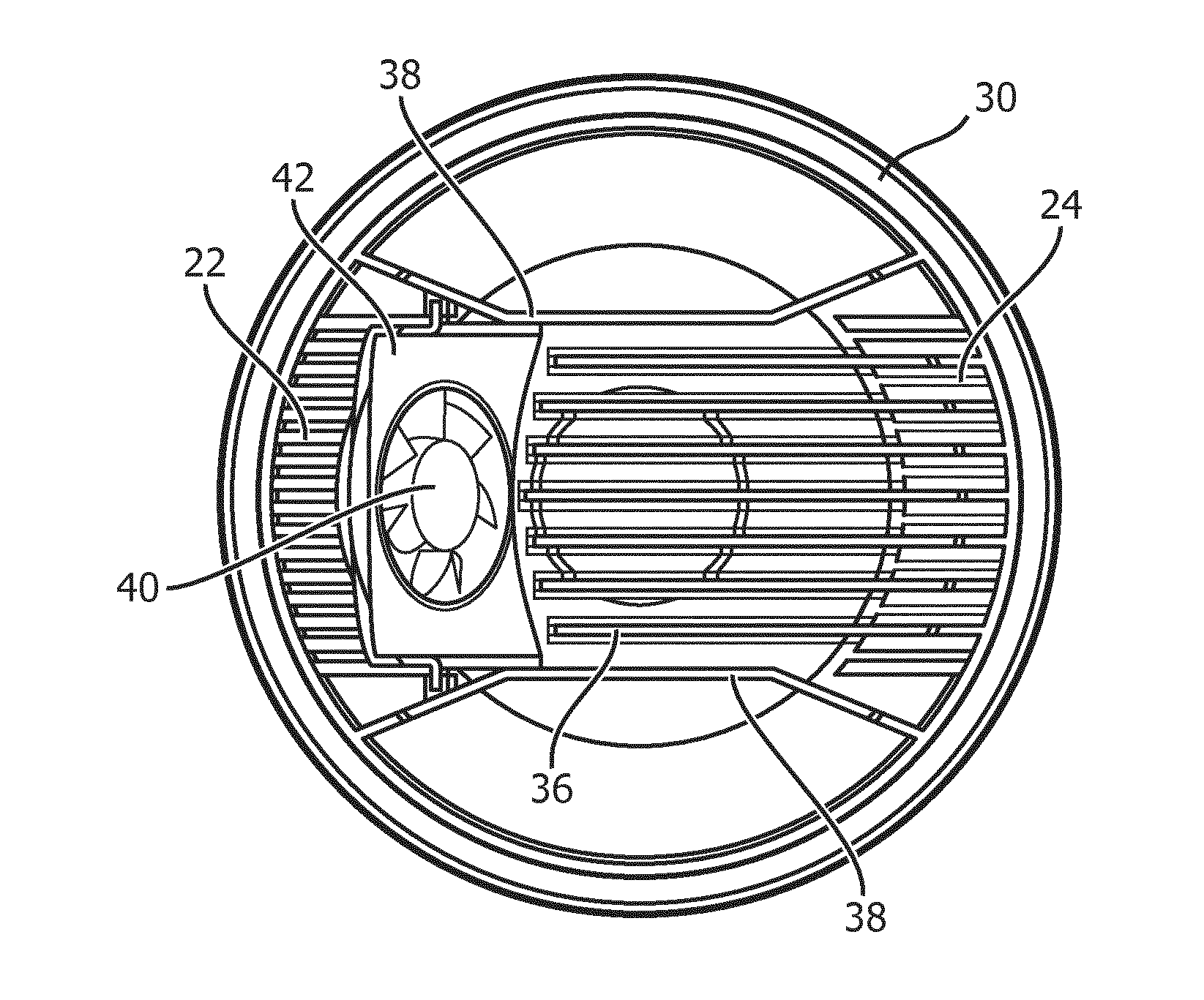
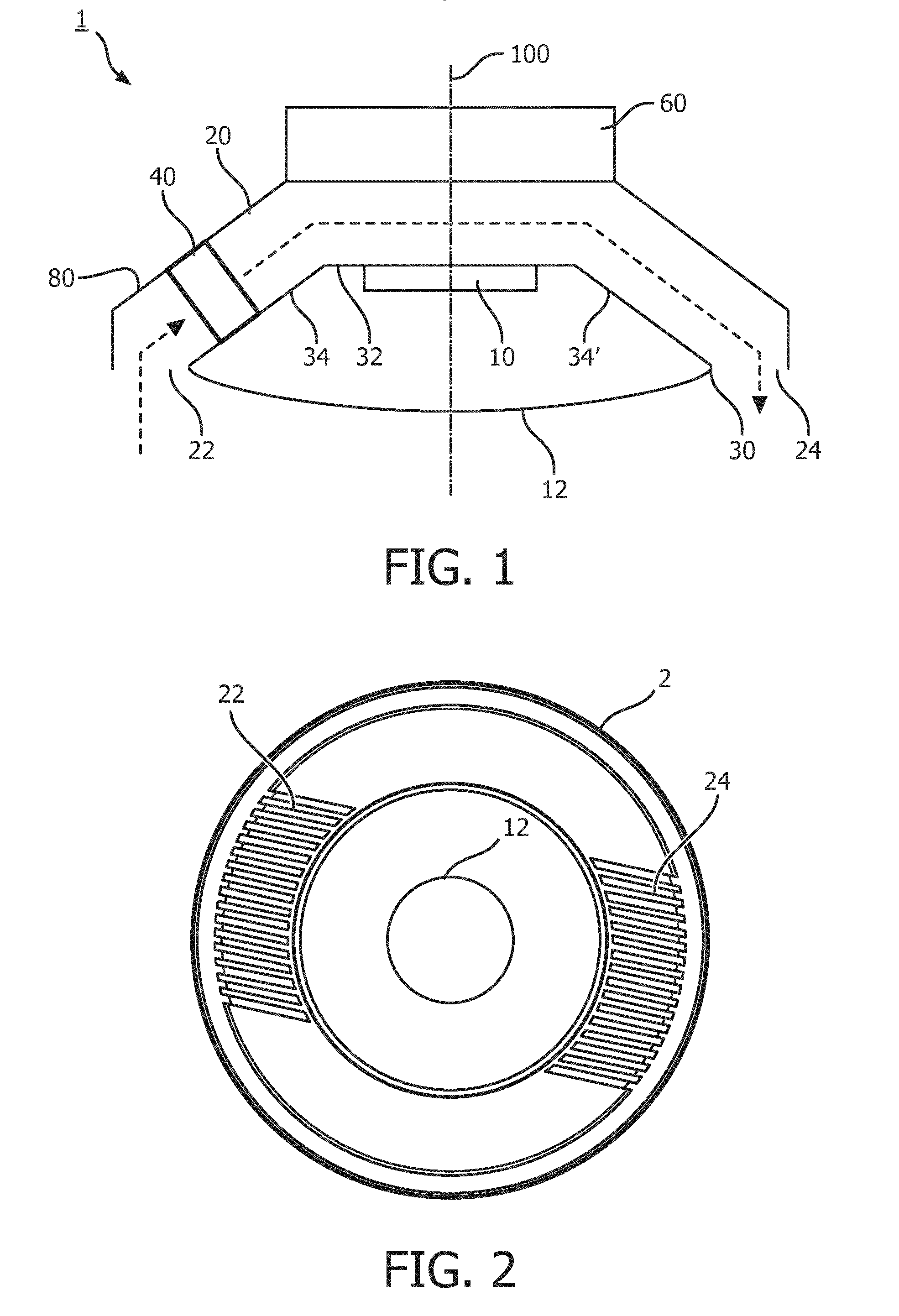
[0041]FIG. 1 schematically depicts a cross section of a lighting device 1 according to an embodiment. The lighting device 1 may for instance be a light bulb or any other suitable lighting device. The lighting device 1 comprises a support structure 30 onto which one or more SSL elements 10 are mounted such that the luminous output of the one or more SSL elements 10 is directed towards a light exit window 12 of the lighting device 1. The one or more SSL elements 10 may for instance be LEDs, e.g. inorganic or organic LEDs. Although not shown specifically, the lighting device 1 may further or alternatively comprise one or more reflective elements for redirecting the luminous output of the one or more SSL elements 10 towards the light exit window 12.

[0042]The ligh...


PUM


Abstract

Disclosed is a lighting device (1) comprising a housing (80), an air inlet (22) and an air outlet (24); a support structure (30) in said housing extending in between said air inlet and said air outlet, said support structure including a section (32) carrying at least one solid state lighting element (10); a conduit (20) from said air inlet to said air outlet such that the conduit extends over the support structure; and a fan (40) mounted in said conduit, wherein the fan is located closer to the air inlet than to the air outlet. A luminaire including such a lighting device is also disclosed.

Description

FIELD OF THE INVENTION[0001]The present invention relates to a lighting device comprising at least one solid state lighting (SSL) element and a cooling fan for cooling the at least one SSL element.[0002]The present invention further relates to a luminaire including such a lighting device.BACKGROUND OF THE INVENTION[0003]Solid state lighting (SSL) is rapidly becoming the norm in many lighting applications. This is because SSL elements such as light emitting diodes (LEDs) exhibit superior lifetime and energy consumption compared to traditional alternatives such as incandescent and fluorescent lighting devices, e.g. light bulbs.[0004]However, there are still difficulties to overcome in order to improve customer satisfaction and increase market penetration. For instance, SSL-based devices are often perceived to create light that is less aesthetically pleasing compared to traditional alternatives. Also, variations in the light produced by SSL-based lighting devices can be unsatisfactory....

Claims


Application Information

Patent Timeline
IPC IPC(8): F21V29/67F21K99/00F21V29/76
CPCF21V29/673F21V29/763F21K9/10F21Y2101/02F21V29/677F21K9/20F21K9/23F21Y2115/10
Inventor LEI, CHENGYONGXIONG, YANWANG, BAO
Owner SIGNIFY HLDG BV
Why Eureka
Try Eureka