Tunable OLED Lighting Source

a technology of oled lighting and oleds, which is applied in the direction of thermoelectric devices, organic semiconductor devices, solid-state devices, etc., can solve the problems of oleds oleds that are prone to a shorter lifespan, and lack of wavelength adjustmen

Active Publication Date: 2016-06-16
UNIVERSAL DISPLAY
View PDF2 Cites 10 Cited by
  • Summary
  • Abstract
  • Description
  • Claims
  • Application Information

AI Technical Summary

Benefits of technology

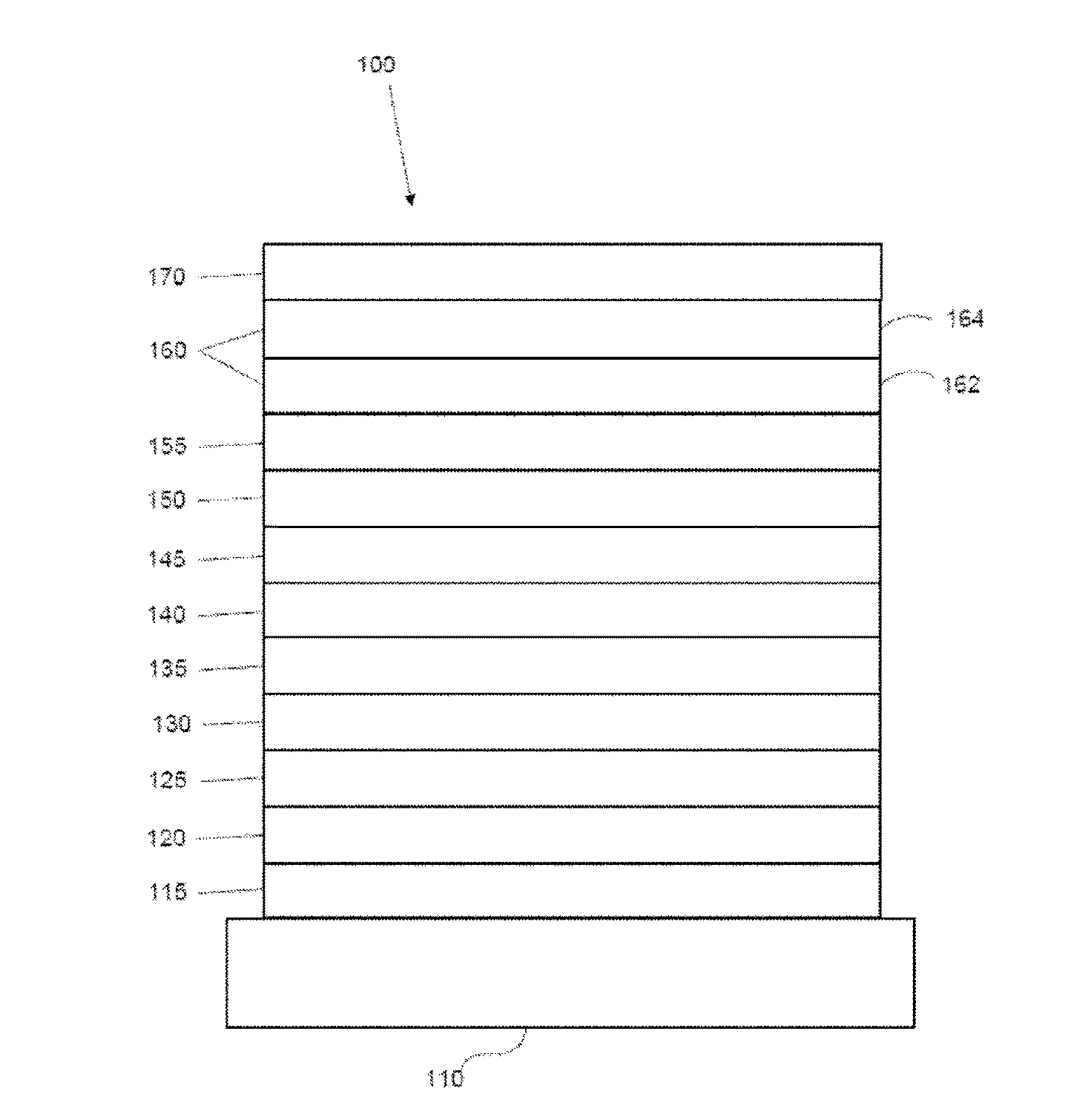
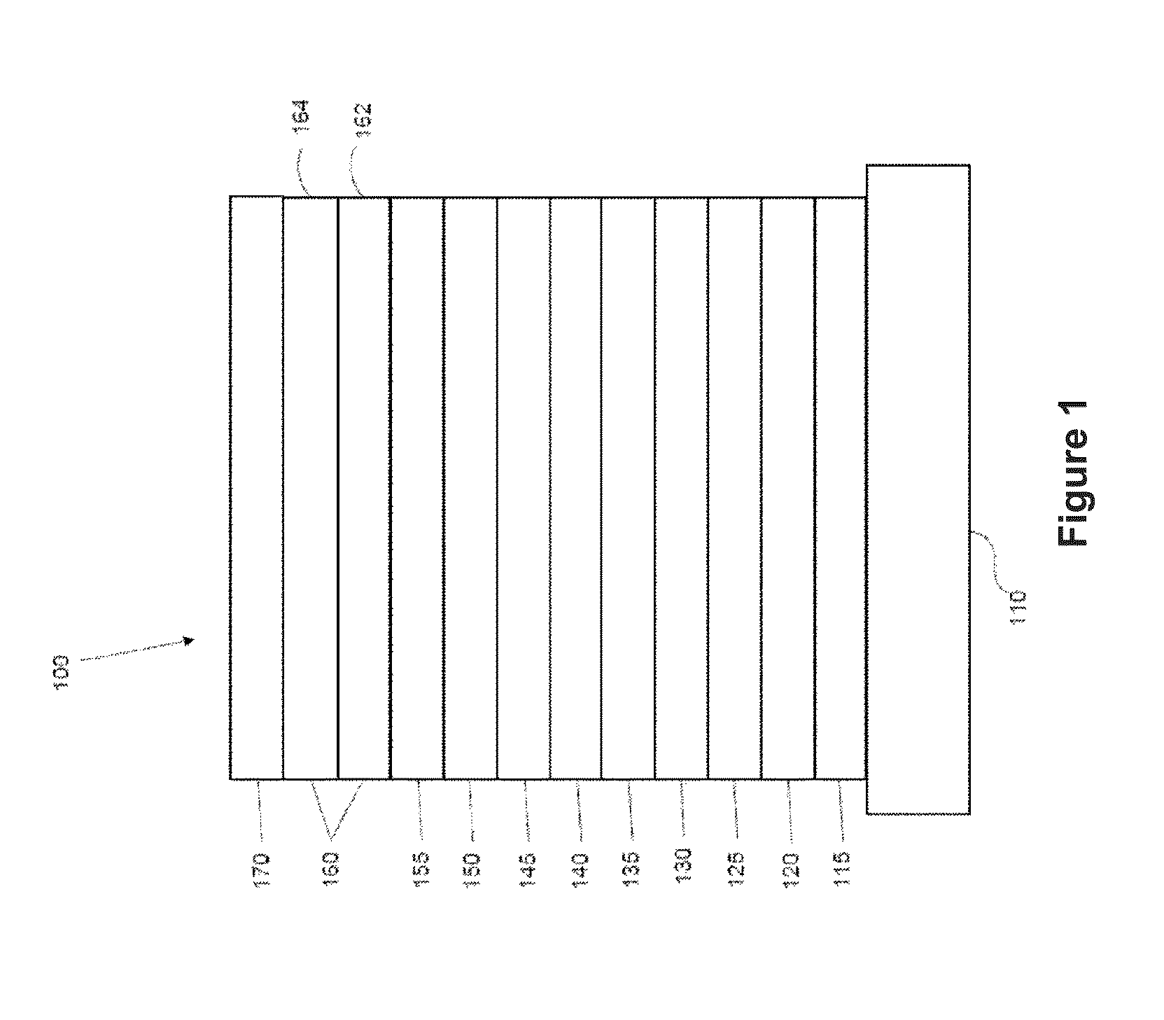
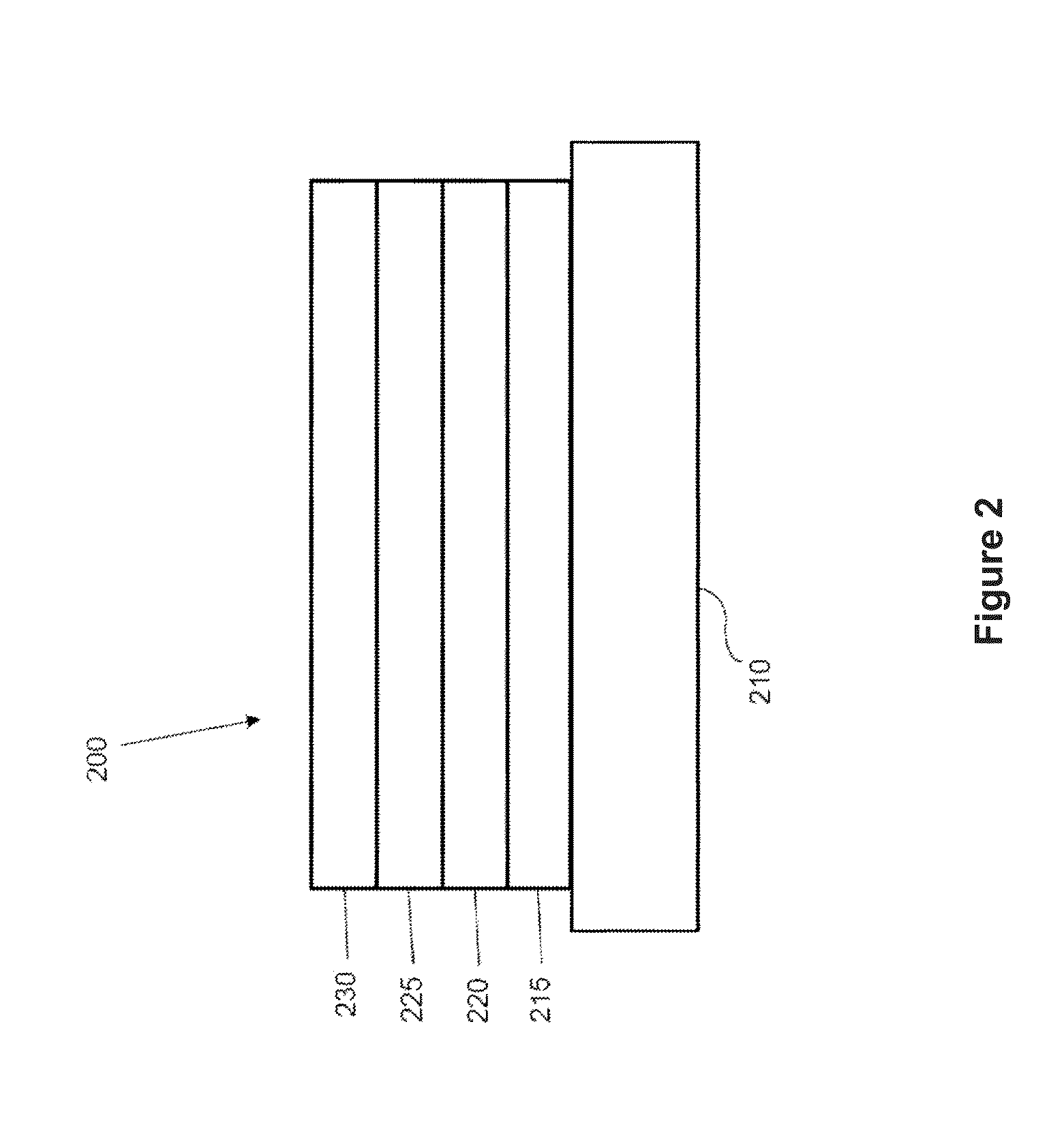
[0018]An OLED device is described, comprising a first top emitting OLED unit disposed over a first substrate, the first OLED unit comprising an anode, a cathode, and at least one organic light emitting layer between the anode and cathode, and a second OLED unit disposed over a second substrate, the second OLED unit comprising an anode, a cathode, and at least one organic light emitting layer between the anode and cathode, wherein the second OLED unit and the second substrate are transparent, and wherein the first and second OLED units are sealed between the first and second substrates. In one embodiment, the first OLED is transparent. In one embodiment, the device includes a controller configured to drive the first and second OLED units independently. In one embodiment, the first and second OLED units are hermetically sealed between the first and second substrates. In one embodiment, the device comprises a gap between the first and second OLED units. In one embodiment, at least a portion of the second OLED unit is in direct contact with the first OLED unit. In one embodiment, the first OLED unit includes a thin film encapsulation. In one embodiment, the second OLED unit includes a thin film encapsulation. In one embodiment, the first and second OLED units each include a thin film encapsulation. In one embodiment, at least one light emitting layer of at least one of the first and second OLED units is an emissive stack. In one embodiment, the device is flexible. In one embodiment, the first substrate comprises a metal material. In one embodiment, the first substrate comprises a glass material. In one embodiment, the first substrate comprises a plastic material. In one embodiment, the second substrate comprises a glass material. In one embodiment, the second substrate comprises a plastic material. In one embodiment one of the first or second OLED units emit blue light and the other OLED unit emits yellow or white light. In one embodiment, the blue emitting OLED unit emits only blue light. In one embodiment, the blue emitting OLED unit emits deep blue light in a weak cavity. In one embodiment, the blue emitting OLED emits a light blue light shiftable to deep blue by a microcavity. In one embodiment, a controller regulates the output of the blue emitting OLED unit based on the output of the yellow or white emitting OLED unit. In one embodiment, the blue emitting OLED unit comprises a striped light emitting pattern of at least two colors. In one embodiment, the at least two colors are deep blue and light blue. In one embodiment, the at least two colors are deep blue and green. In one embodiment, the at least two colors are independently driven by a controller. In one embodiment, the at least two colors are formed from at least two different light emitting materials. In one embodiment, the device comprises at least one sensor for recording light color. In one embodiment, the controller regulates the output of light from at least one of the first and second OLED units based on a signal received from the at least one sensor. In one embodiment, the device comprises a reflective layer between the first substrate and the first OLED unit. In one embodiment, the anode of the first OLED unit is reflective and is positioned between the at least one light emitting layer of the first OLED unit and the first substrate. In one embodiment, the first substrate is reflective. In one embodiment, the controller is capable of adjusting the luminance output of the device while maintaining substantially consistent color temperature output of the device by regulating at least one output of the first or second OLED units. In one embodiment, the controller is capable of adjusting the color temperature output of the device by regulating at least one output of the first or second OLED units. In one embodiment, the device comprises at least one out-coupling enhancing technology. In one embodiment, the at least one out-coupling outcoupling enhancing technology is selected from the group consisting of a structured film, a lens, a diffuser, and a scattering layer. In one embodiment, the at least one organic light emitting layers of the first and second OLED units are index matched. In one embodiment, a product comprises the device, the product selected from the group consisting of: a luminaire, a general illumination device, and a sign.

Problems solved by technology

While OLED luminaires and other devices have many of the aforementioned advantages, they lack the ability to adjust wavelengths, either to achieve a desired color temperature output or to preserve the life expectancy of an OLED, especially blue light OLEDs which are prone to a shorter lifespan.
Current attempts to achieve these features have required the patterning of individual colored OLED emitters and are susceptible to lower lifespans.

Method used


Image

  • Tunable OLED Lighting Source
  • Tunable OLED Lighting Source
  • Tunable OLED Lighting Source

Examples


Embodiment Construction

[0025]Unless defined otherwise, all technical and scientific terms used herein have the same meaning as commonly understood by one of ordinary skill in the art to which this invention belongs. As used herein, each of the following terms has the meaning associated with it as described.

[0026]The articles “a” and “an” are used herein to refer to one or to more than one (i.e., to at least one) of the grammatical object of the article. By way of example, “an element” means one element or more than one element.

[0027]“About” as used herein when referring to a measurable value such as an amount, a temporal duration, and the like, is meant to encompass variations of ±20%, ±10%, ±5%, ±1%, or ±0.1% from the specified value, as such variations are appropriate.

[0028]Throughout this disclosure, various aspects of the invention can be presented in a range format. It should be understood that the description in range format is merely for convenience and brevity and should not be construed as an inf...


PUM


Abstract

Described herein are devices and methods related to lighting systems that are color tunable and have a long lifetime. In certain embodiments, the device comprises two independently controlled phosphorescent OLED lighting panels coupled together in one package to emit light in one direction. In certain embodiment, aspects of the device are tunable, such as RGB color, color temperature, and luminance.

Description

CROSS-REFERENCE TO RELATED APPLICATIONS[0001]This application claims priority to U.S. Patent Application Ser. No. 62 / 092,481, filed Dec. 16, 2014, the entire contents of which are incorporated herein by reference.PARTIES TO A JOINT RESEARCH AGREEMENT[0002]The claimed invention was made by, on behalf of, and / or in connection with one or more of the following parties to a joint university corporation research agreement: Regents of the University of Michigan, Princeton University, University of Southern California, and the Universal Display Corporation. The agreement was in effect on and before the date the claimed invention was made, and the claimed invention was made as a result of activities undertaken within the scope of the agreement.FIELD OF THE INVENTION[0003]The present invention relates to lighting systems and devices comprising organic light emitting diodes that are color tunable and have a long lifetime, as well as methods for making the same.BACKGROUND[0004]Opto-electronic ...

Claims


Application Information

Patent Timeline
Patent Type & Authority Applications(United States)
IPC IPC(8): H01L25/04H01L51/52H01L25/16H01L51/50
CPCH01L25/048H01L51/5004H01L51/5036H01L2251/5353H01L51/5271H01L25/167H01L51/5253H01L2924/0002H10K59/128H10K50/841H10K50/856H01L2924/00
Inventor HACK, MICHAELWEAVER, MICHAEL S.
Owner UNIVERSAL DISPLAY
Why Eureka
Try Eureka