Override-based, predictive speed capping

a technology of override and prediction, applied in the direction of programmed manipulators, instrumentation, programme control, etc., can solve the problems of not immediately implementing or implementing predetermined nominal override values, and achieve the effect of preventing the speed of several alternative tcps and preventing the overriding of monitoring limits

Active Publication Date: 2016-06-23
KUKA ROBOTER
View PDF1 Cites 1 Cited by
  • Summary
  • Abstract
  • Description
  • Claims
  • Application Information

AI Technical Summary

Benefits of technology

[0021]The simulation preferably takes place based at least on a current pose of the manipulator and / or a path plan. The prediction or simulation of the halting movement can also advantageously be based on other states of the manipulator, of the robot system, as well as the surrounding environment. This permits a reliable operation of the manipulator.
[0022]The predetermined monitoring limit preferably comprises at least one of the following: a predetermined working space limit, with the working space limit more preferably being defined in Cartesian or axis-specific coordinates, a predetermined maximum axis speed for at least one axis of the manipulator, a predetermined maximum tool speed, and / or a predetermined maximum flange speed or a predetermined maximum tool center point speed. The person skilled in the art will understand that a manipulator can be monitored and controlled on the basis of various monitoring limits or monitoring criteria. In particular, the monitoring limits can be set with reference to an operating mode. Depending on the use and the design of the manipulator, the person skilled in the art can select suitable monitoring limits and thus predetermine them for the method according to the invention. This means that, for example, critical elements of the robot kinematics (such as the speed of the joint positions, for example) can be limited. In addition, the speeds of several alternative TCPs, for example, can be suitably limited. In addition, the method according to the invention also allows limitation of values based on higher axis derivations (such as axis acceleration, for example) and variables derivable therefrom (such as motor torques and drive torques, for example) and prevention of any exceeding of such values.
[0023]The simulation of the halting movement preferably comprises a calculation of a speed of the manipulator and / or a calculation of an actual override value and / or a calculation of an actual state of the manipulator for the at least one cycle tn following the current cycle. From the trend of these values, robot poses, for example, can be predicted in an exact Cartesian and axis-specific manner up until the stop of the manipulator (i.e. up until the actual override value of zero is reached). From this position trend, all relevant monitoring variables can be easily and precisely predicted up until the stop of the manipulator.
[0024]The simulation of the halting movement of the manipulator is preferably carried out for every cycle tn following the current cycle up until a simulated standstill of the manipulator. The halting movement is thus simulated for all cycles tn in which the manipulator has not yet come to a standstill, i.e. there is an actual override value greater than zero, for example. However, the simulation is preferably ended in the event of detection of a violation of a monitoring limit. The halting movement of the manipulator can thus be directly initiated in an efficient manner.
[0025]The method according to the invention preferably also comprises, preferably before the simulation of the halting movement, an identification, at the beginning of the current cycle, of an actual state of the manipulator for the current cycle, based at least on a nominal speed for the current cycle. In addition, the method according to the invention preferably comprises a determination of whether, based on the identified actual state of the manipulator, a predetermined monitoring limit is violated, and a reduction in response to the determination of the nominal speed for the current cycle. It is thus checked whether, based on the nominal speed, which is available to the robot controller, for example, a monitoring limit is violated in the current cycle. The nominal speed can preferably comprise a nominal override. Through a reduction of the nominal speed for the current cycle, such an exceeding of a monitoring limit can thus be prevented.
[0026]An initiation of a halting movement on the basis of the determination is not required, since the permissibility of a movement during the current cycle was already checked in accordance with the method according to the invention in a preceding cycle. It is thus advantageously ensured that no monitoring limits are violated during the current cycle and that the initiation of a halting movement in the immediately following cycle would not result in any impermissible violations of monitoring limits.

Problems solved by technology

The person skilled in the art will understand that the nominal speed can be a parameter predetermined for the robot controller, which may not be able to be implemented in a cycle, since joint drives, for example, cannot apply the forces and torque it requires.
Similarly, a predetermined nominal override value may be not immediately implemented or not implemented in a single cycle.

Method used


Image

  • Override-based, predictive speed capping
  • Override-based, predictive speed capping

Examples


Embodiment Construction

[0031]The present invention is described in greater detail below with reference to the accompanying figure, in which:

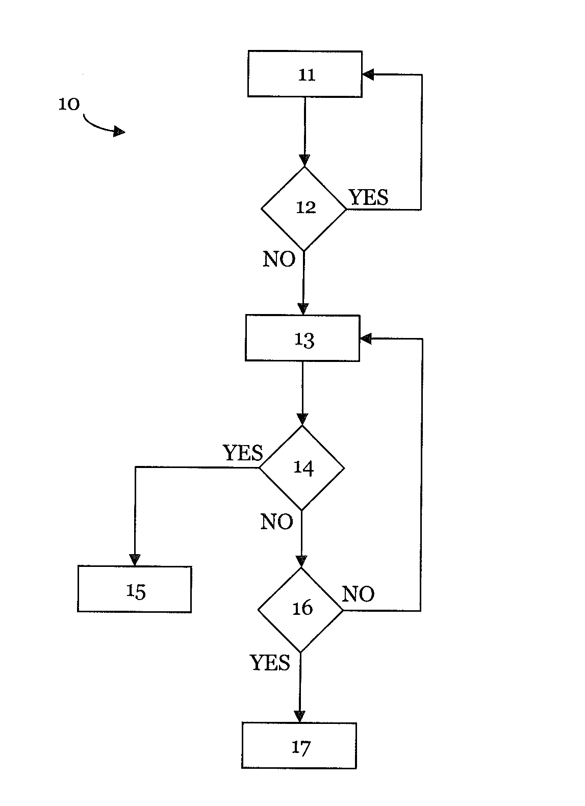
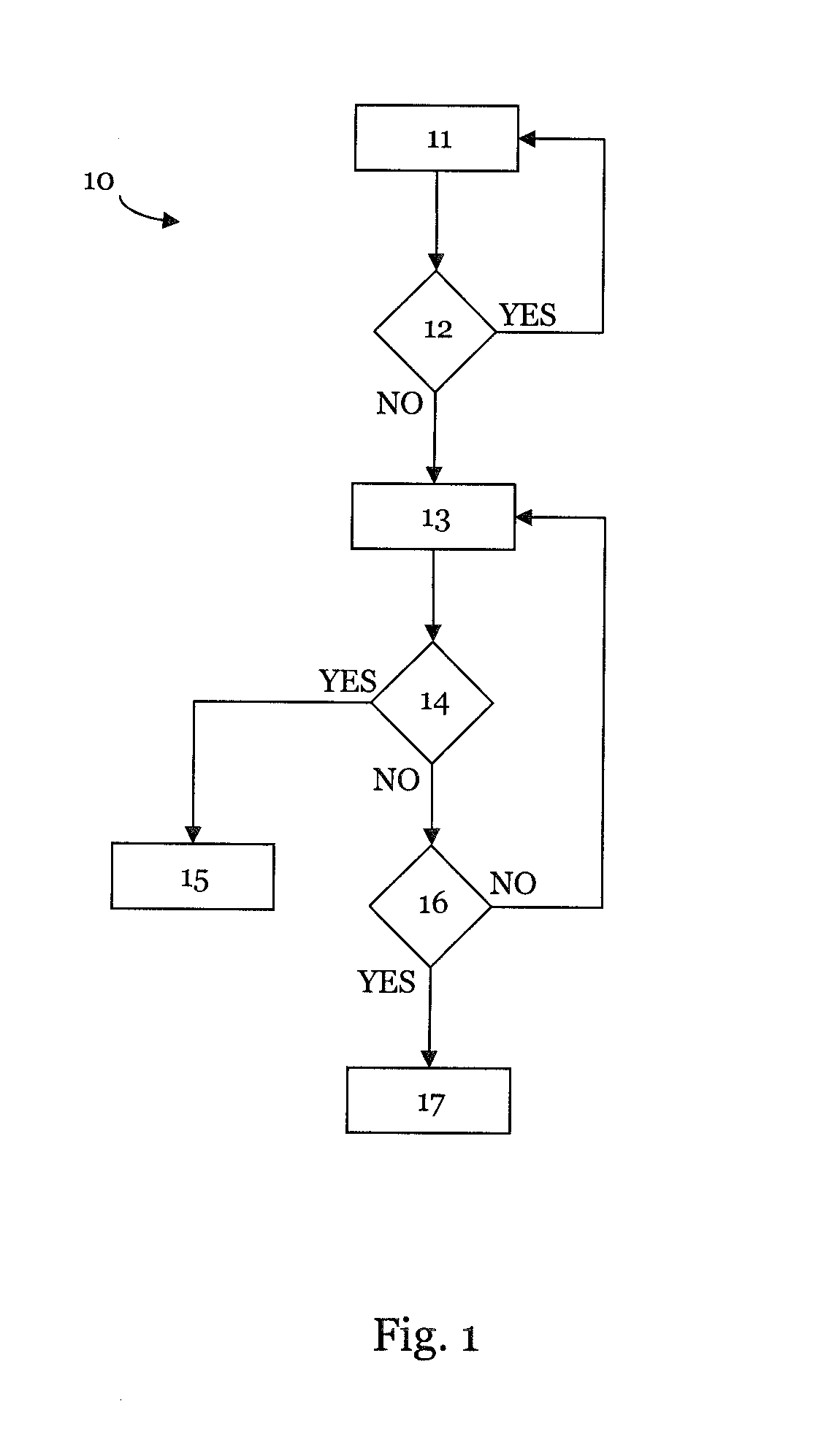
[0032]FIG. 1 shows a schematic representation of the sequence of a method according to the invention for controlling a manipulator.

[0033]FIG. 1 is a schematic and exemplary depiction of the sequence of a method 10 according to the invention for controlling a manipulator. The depicted processes preferably take place at the beginning of a current cycle, hereafter referred to as cycle to.

[0034]The method 10 begins in step 11, wherein, in cycle to, a new actual override value is identified, which results from a predetermined nominal override value. Alternatively, it is also possible to identify what actual path speed would result based on a predetermined nominal path speed. Based on the identified actual override value, Cartesian and axis-specific robot positions and all relevant, i.e. to be monitored, derivations of this position data are identified for the cycle to.

[003...


PUM


Abstract

A method for controlling a manipulator, with the method being particularly suitable for the respecting of predetermined monitoring limits. The method operates by initiating a halting movement or a speed capping based on an identified actual override trend, and is thus suitable, in particular, for path movements by means of spline interpolation.

Description

[0001]This application claims the benefit of priority under 35 §119(a) to German Patent Application No. 10 2014 226 914.8, filed on Dec. 23, 2014.1. TECHNICAL FIELD[0002]The present invention relates to a method for controlling a manipulator, in particular in order to ensure that predetermined monitoring limits are respected.2. TECHNICAL BACKGROUND[0003]Robots, and in particular industrial robots, are freely programmable, program-controlled manipulation devices. The actual robot mechanics is referred to as a manipulator. This can consist of a number of moveable, interconnected links or axes, which define the kinematic chain of the robot. The kinematic chain usually extends from the foot of the robot to the flange of the robot, or, if provided, to a tool connected to the flange.[0004]The movement of the individual axes of a robot can take place by means of a targeted control of drives, which are connected to the individual components of the manipulator. For a movement between individ...

Claims


Application Information

Patent Timeline
Patent Type & Authority Applications(United States)
IPC IPC(8): B25J9/16
CPCB25J9/1671Y10S901/28Y10S901/16Y10S901/02B25J9/1676G05B2219/39097G05B2219/39098G05B2219/40475
Inventor TRONNIER, HOLGERWIEDEMANN, GUNTHERBURKHART, STEFANAURNHAMMER, ANDREASHUTTENHOFER, MANFRED
Owner KUKA ROBOTER
Why Eureka
Try Eureka