Aircraft wing torsion box, aircraft wing, aircraft and supporting member for use therein

Active Publication Date: 2016-06-23
AIRBUS OPERATIONS LTD
View PDF1 Cites 11 Cited by
  • Summary
  • Abstract
  • Description
  • Claims
  • Application Information

AI Technical Summary

Benefits of technology

[0013]The wing box of the present invention may provide a simpler wing box by using a support member that provide

Problems solved by technology

Such wing boxes are complex and comprise many individual components.
Such an arrangement may be heavy, which is undesirable.
Furthermore, the conventional wing box

Method used


Image

  • Aircraft wing torsion box, aircraft wing, aircraft and supporting member for use therein
  • Aircraft wing torsion box, aircraft wing, aircraft and supporting member for use therein
  • Aircraft wing torsion box, aircraft wing, aircraft and supporting member for use therein

Examples


Embodiment Construction

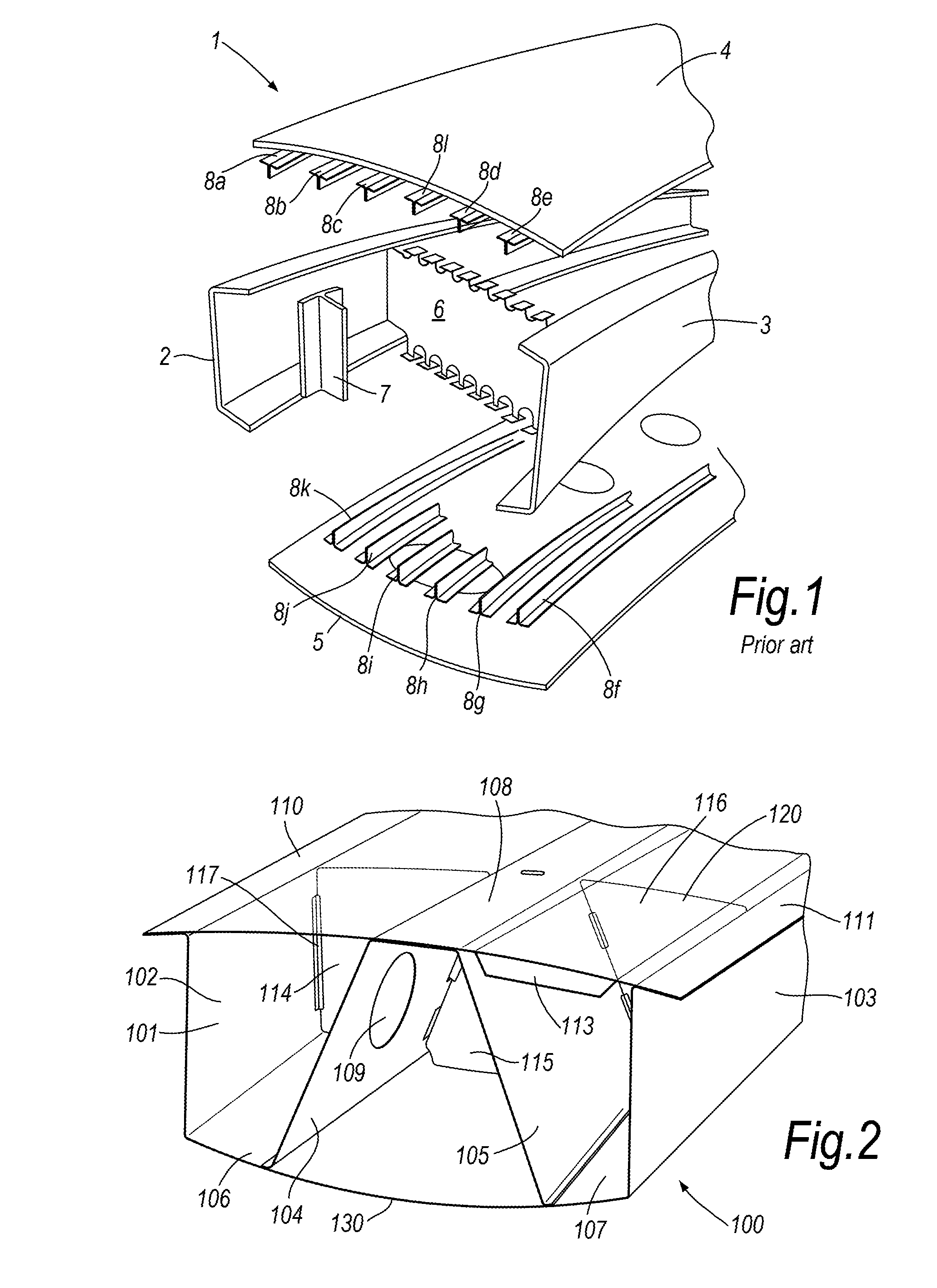
[0059]FIG. 1 shows a known wing box 1 (also referred to as a wing torsion box) comprising a front spar 2 and rear spar 3 which support upper and lower wing skins 4, 5. Ribs 6 (a representative one of which is shown) extend rearward from the front of the wing box 1. Each rib is attached to a rib-spar post 7, a representative one of which is shown. The rib-spar post 7 is attached to a respective spar 2. Stringers 8a to 8l provide structural support to the wing skins 4, 5. The stringers are attached to the ribs 6.

[0060]FIG. 1 shows that the known wing box is complex and involves the attachment of many different discrete components which is time-consuming. Furthermore, the attachment of many different components requires the use of many bolts, resulting in the exterior of the aircraft having many bolt heads, providing many potential lightning strike sites.

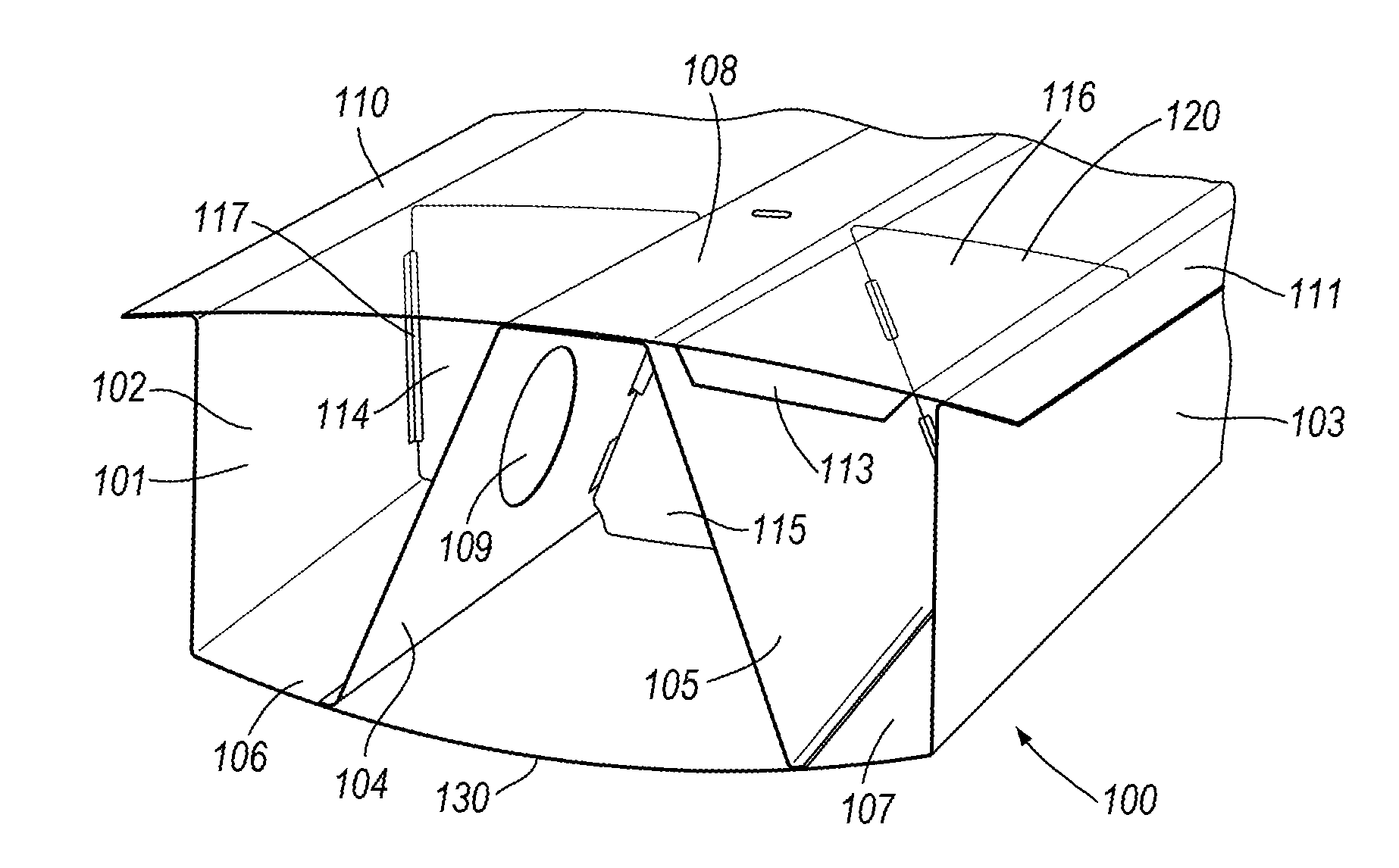
[0061]FIG. 2 is a schematic “see through” perspective view of a wing box (being a wing torsion box) in accordance with an embodiment ...


PUM


Abstract

An aircraft wing torsion box having a front associated with a leading portion of the wing torsion box and a rear associated with a trailing portion of the wing torsion box. The wing torsion box includes a support member having a front spar and a rear spar and a connecting portion between the front and rear spars, the connecting portion includes at least one interposing spar, at least one portion of upper wing skin; and at least one portion of lower wing skin, and at least one portion of the upper wing skin and at least one portion of the lower wing skin being supported by the support member.

Description

BACKGROUND OF THE INVENTION[0001]This application claims priority to United Kingdom (GB) patent application 1422938.9 filed Dec. 22, 2014, the entirety of which is incorporated by reference.BACKGROUND OF THE INVENTION[0002]The present disclosure relates to an aircraft wing box, in particular an aircraft wing torsion box (also referred to as a wing box).[0003]The present invention concerns aircraft. More particularly, but not exclusively, this invention concerns an aircraft wing torsion box. The invention also concerns an aircraft wing, an aircraft comprising such an aircraft wing torsion box or aircraft wing and a support member for use in such an aircraft wing torsion box or aircraft wing.[0004]A conventional wing torsion box comprises separate front and rear wing spars extending along the length of the wing box, with ribs extending between the front and rear wing spars, with separate rib-spar posts being provided to help hold the spars and ribs together. Separate stringers run the...

Claims


Application Information

Patent Timeline
IPC IPC(8): B64C3/18B64C3/26
CPCB64C3/26B64C3/18B64C3/00B64C3/20B64C3/185B64C1/26
Inventor EVANS, STEVEN
Owner AIRBUS OPERATIONS LTD
Why Eureka
Try Eureka