Installation for drying a damp non-woven web

Active Publication Date: 2016-06-23
RIETER PERFOJET
View PDF14 Cites 3 Cited by
  • Summary
  • Abstract
  • Description
  • Claims
  • Application Information

AI Technical Summary

Benefits of technology

[0020]It is now the first perforated sheet that gets clogged most quickly. That is why there is provision, according to an embodiment of the invention, to mount it in a movable drawer which preferably has a handle outside the fitting. In order to replace the first perforated sheet, it is no longer necessary to unclamp the fittin

Problems solved by technology

It is found that the non-woven web thus o

Method used


Image

  • Installation for drying a damp non-woven web
  • Installation for drying a damp non-woven web
  • Installation for drying a damp non-woven web

Examples


Example

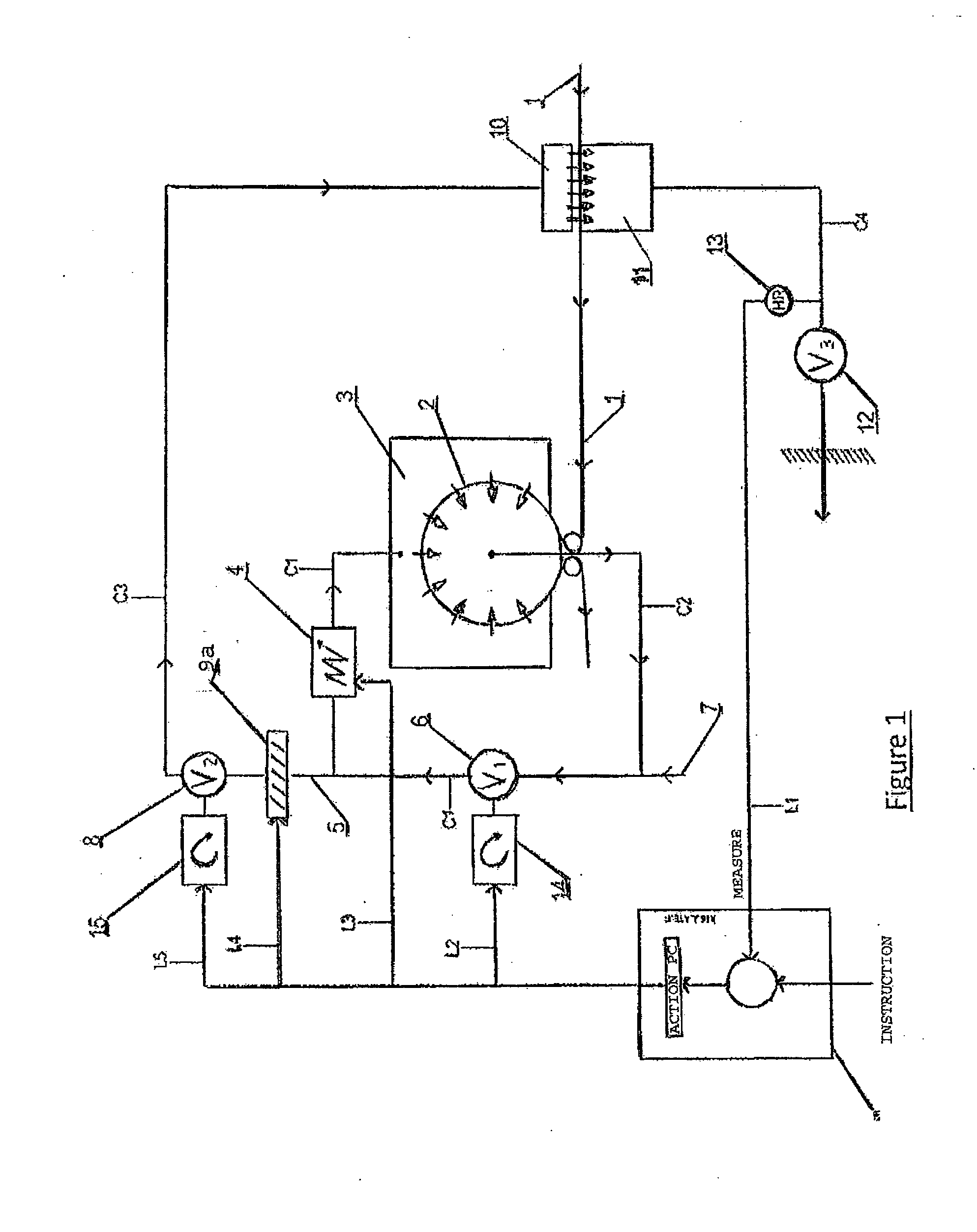
[0027]In FIG. 1, the dried web 1 circulates around a drum 2 or on a conveyor.

[0028]Hot air under pressure is injected through an inlet conduit C1 in the hood 3 thanks to a fan V16 (called main fan) and a heat source 4 which heats up the air. This heat source 4 can be, for example, a gas burner or an (oil, air, water or electrical) heat exchanger.

[0029]This hot air then passes over the damp web and the drum 2 (or the conveyor cloth): by means of this process, the water contained in the web is evaporated as the web advances on the drum 2 (or on the conveyor). The air which has passed over the web has been cooled and laden with moisture. It is then taken in by an extraction conduit C2 inside the drum 2 by means of the fan V16 and heated up anew by the heat source 4 and reinjected into the loop and so on.

[0030]The heat source 4 can be positioned upstream or downstream of the fan V16. It is preferably positioned downstream, as shown in the figure, in the case of an exchanger and upstream...


PUM


Abstract

An installation for drying a non-woven web includes a device (10, 11), a diffusion chamber (10) having an outlet fitting (21) in which there is mounted a perforated sheet (24) creating a drop in pressure.

Description

TECHNICAL FIELD[0001]The present invention relates to installations for drying a non-woven web.BACKGROUND ART[0002]In U.S. Pat. No. 6,551,461 B2 a process is described for drying a damp web by passing across the damp web, displaced by a means of transport, in an oven hot air which is thus dampened, by reheating a first portion of the dampened air and by passing it back across the damp web in the oven and by passing a second portion of the dampened air across the displaced damp web in a drying device upstream of the oven in the direction of displacement of the web.[0003]It is found that the non-woven web thus obtained is not dried in a uniform manner.DISCLOSURE OF THE INVENTION[0004]The invention remedies this by means of an installation for drying a non-woven web, characterised in that it comprises:[0005]a fan,[0006]a heating oven having an inlet and an outlet,[0007]an inlet conduit which connects the delivery of the fan with the inlet of the oven and sends delivered air to the inle...

Claims


Application Information

Patent Timeline
IPC IPC(8): D21F5/18
CPCD21F5/18F26B21/001F26B13/16F26B21/04F26B21/12F26B23/002F26B21/004Y02P70/10
Inventor SCHMIT, LAURENTPLANET, ALAIN
Owner RIETER PERFOJET
Why Eureka
Try Eureka