Engine Air Pre Cleaner Evacuation System for Work Machine

a technology for cleaning systems and work machines, applied in the field of work machines, can solve problems such as damage to the fan housing, reducing the efficiency of the aspirator fan, and affecting and achieve the effect of improving the performance of the aspirator

Active Publication Date: 2016-06-23
BLUE LEAF I P
View PDF3 Cites 4 Cited by
  • Summary
  • Abstract
  • Description
  • Claims
  • Application Information

AI Technical Summary

Benefits of technology

The present invention relates to an improvement for a work machine that has an aspirator fan. A new device called a venturi element is added after the fan and connects with the engine's air cleaning system. This change makes sure that the aspirator works even better than before.

Problems solved by technology

The technical problem addressed in this patent text is the need for a reliable and efficient air pre-cleaner for work machines, especially agricultural machines, to remove larger particles of dust, straw, and other contaminants from the air prior to its introduction in the engine's air filter. Existing solutions have proven to be unstable and potentially dangerous, while the addition of an aspirator in the engine exhaust or the use of a venturi device to join the particle stream from the pre-cleaner with the debris stream from the radiator reduces the efficiency of the aspirator fan and may cause damage to the fan and fan housing. The solution presented in this patent text is a new and improved design for the aspirator fan that separates the particle stream from the pre-cleaner output, but it is technically complex and expensive.

Method used


Image

  • Engine Air Pre Cleaner Evacuation System for Work Machine
  • Engine Air Pre Cleaner Evacuation System for Work Machine

Examples


Embodiment Construction

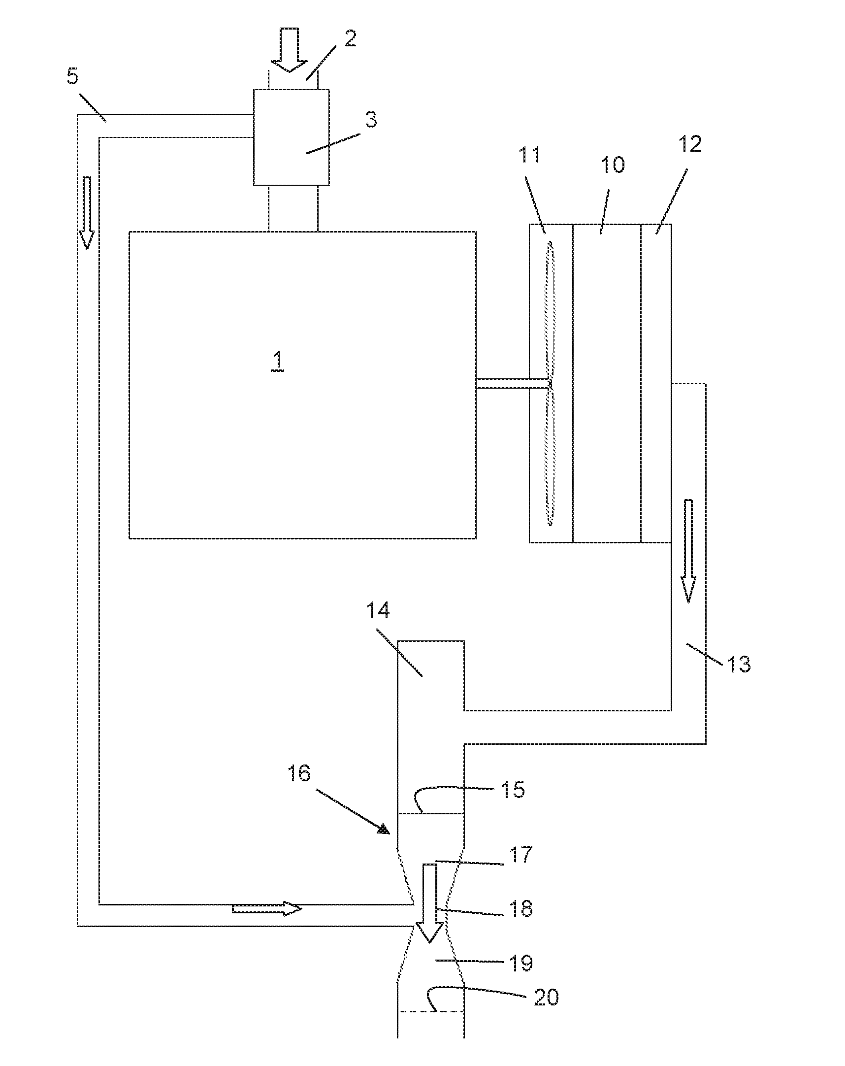
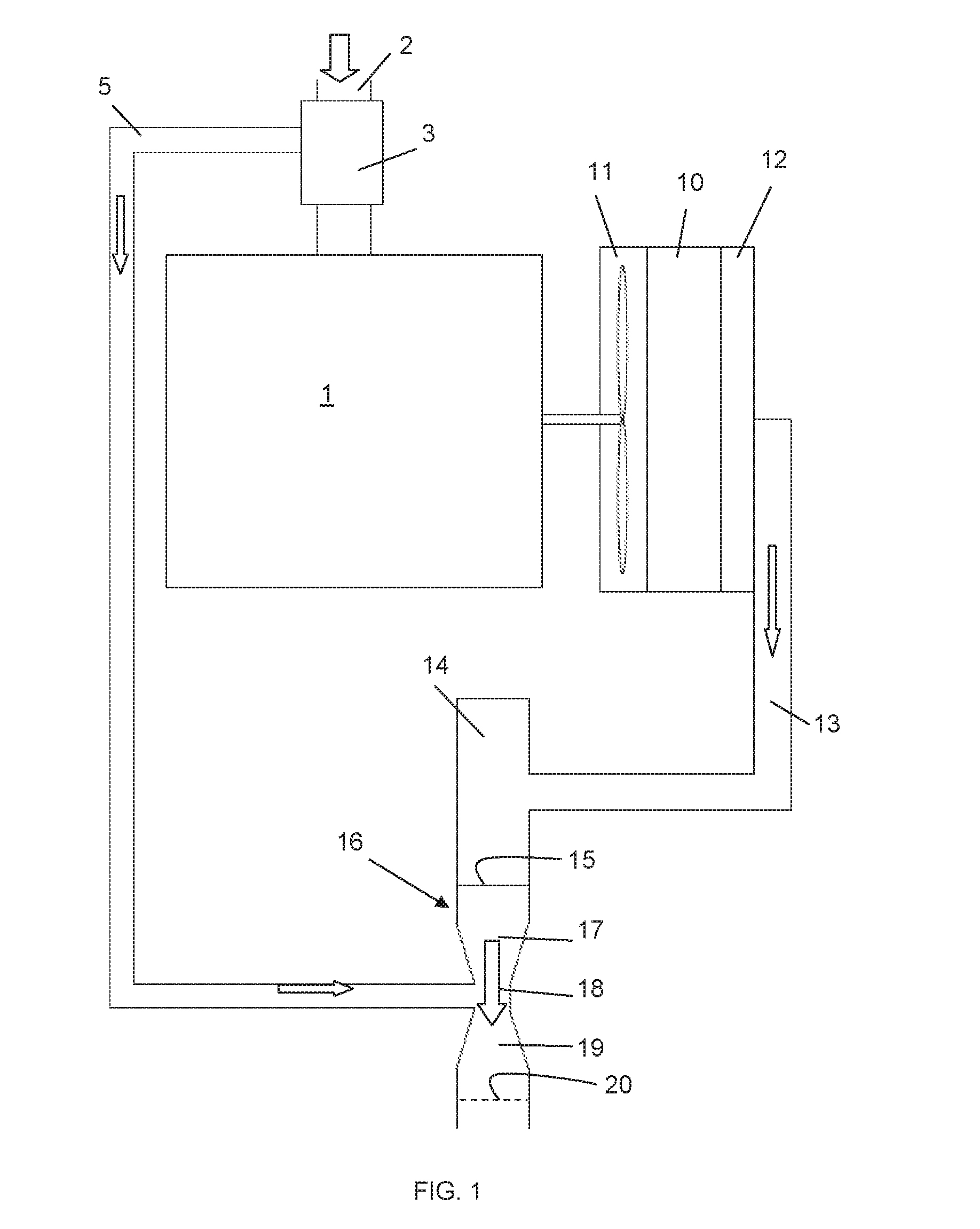
[0006]Preferred embodiments will now be described with reference to the drawings. The detailed description is not limiting the scope of the invention, which is defined only by the appended claims. FIG. 1 is a schematic view of the cooling air supply system and engine pre-cleaner system of an internal combustion engine in a work machine according to the invention. The arrows indicate the direction of flow through various components. The expressions ‘upstream’ and ‘downstream’ are to be understood with regard to the thus indicated flow directions. According to a preferred embodiment, the work machine is a combine harvester, but the invention is applicable to any work machine that is operable in similar dusty or contaminated environments, such as any kind of forestry or construction vehicle. The engine 1 is visible, supplied with air through air inlet 2. An air pre-cleaner 3 is mounted in the inlet duct, usually upstream of an air filter (not shown). The pre-cleaner may operate accordi...


PUM


Abstract

A work machine with an internal combustion engine is provided with an air inlet for receiving combustion air, wherein an air pre-cleaner is mounted in the inlet, a radiator, a cooling air fan and a debris removal means, configured to remove debris from a flow of air produced by the cooling air fan through the radiator, the removal means comprising a screen for collecting the debris, and an aspirator for aspirating the debris away from the screen, and a venturi element mounted downstream of the aspirator, and having an inlet portion, a throat portion and an outlet portion, wherein a duc is mounted between the engine air pre-cleaner and the throat portion, so that particles removed by the pre-cleaner flow towards the throat portion, and out through the outlet portion of the venturi element, together with the aspirated debris.

Description


Claims


Application Information

Patent Timeline
Owner BLUE LEAF I P
Why Eureka
Try Eureka