Supercharge Your Innovation With Domain-Expert AI Agents!

Fluid pressure cylinder

a technology mounting plate, which is applied in the direction of safety/regulation devices, machines/engines, mechanical equipment, etc., can solve the problems of deteriorating mountability of equipment, and achieve the effect of improving the mountability of fluid pressure cylinder

Active Publication Date: 2016-06-23
KYB CORP
View PDF8 Cites 9 Cited by
  • Summary
  • Abstract
  • Description
  • Claims
  • Application Information

AI Technical Summary

Benefits of technology

The invention aims to make it easier to mount a fluid pressure cylinder that has a displacement sensor built in.

Problems solved by technology

Therefore, a mounting length of the fluid pressure cylinder is increased by the length of the sensor body, thereby deteriorating mountability to the equipment.

Method used


Image

  • Fluid pressure cylinder
  • Fluid pressure cylinder

Examples


Embodiment Construction

[0010]With reference to the drawing, an embodiment of the present invention will be described.

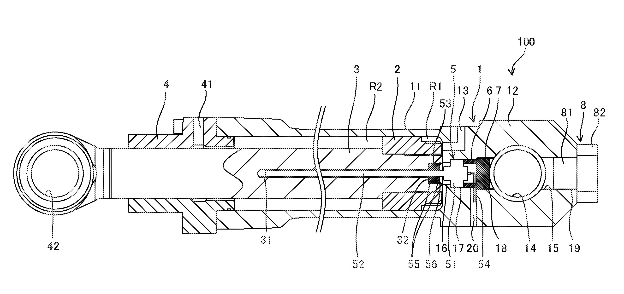
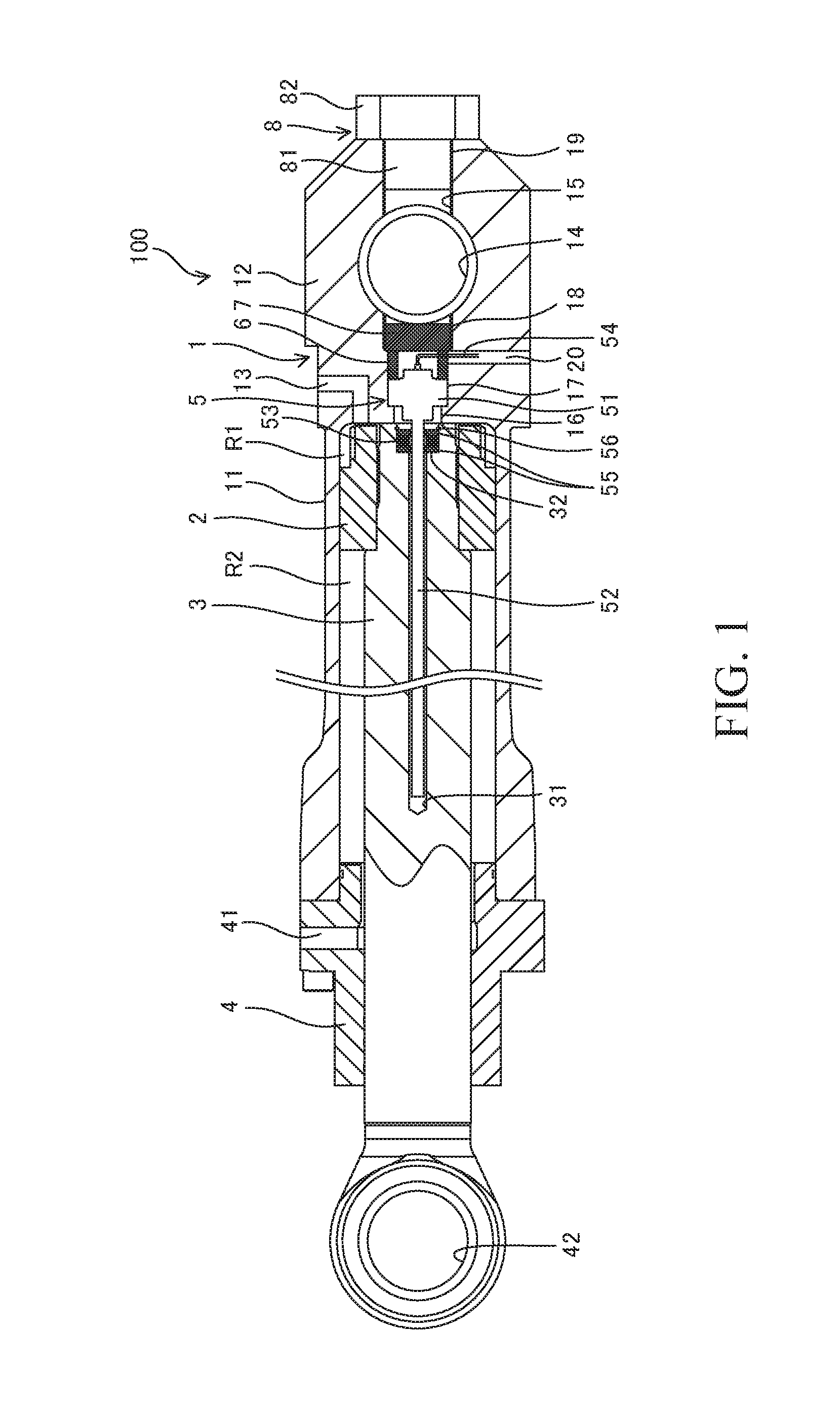
[0011]FIG. 1 is a sectional view showing a fluid pressure cylinder 100 in this embodiment.

[0012]The fluid pressure cylinder 100 is the fluid pressure cylinder 100 of a double acting type including a cylinder tube 1 having a bottomed cylindrical shape, a piston 2 that is inserted into the cylinder tube 1 in a freely slidable manner, a piston rod 3 that is linked to the piston 2 at a tip end thereof on the insertion side into the cylinder tube 1, a cylinder head 4 that is fit to an open end of the cylinder tube 1 and supports the piston rod 3 in a slidable and rotatable manner, and a displacement sensor 5 that detects relative displacement between the piston rod 3 and the cylinder tube 1.

[0013]The cylinder tube 1 includes a hollow tube 11 that defines a fluid chamber therein and a bottom portion 12 that is provided on a base portion of the tube 11. The fluid chamber is partitioned by the pist...


PUM


Abstract

A fluid pressure cylinder includes a cylinder tube, a piston rod, and a displacement sensor. A bottom portion of the cylinder tube has: a pin hole formed in a direction orthogonal to a center axis; and a through hole penetrating the bottom portion through the pin hole. The displacement sensor has: a sensor body disposed on inner side of the pin hole in the through hole; a sensor rod provided so as to extend from the sensor body; and an annular magnet relatively movable with respect to the sensor rod. The through hole has: a reduced-diameter portion; and a female screw portion that has a female screw formed on an inner circumference of the female screw portion. The sensor body is fixed by being pressed by a plug that is screwed into the female screw portion and by being engaged with the reduced-diameter portion.

Description

TECHNICAL FIELD[0001]The present invention relates to a fluid pressure cylinder.BACKGROUND ART[0002]A fluid pressure cylinder includes a cylindrical cylinder tube, a piston that is inserted into the cylinder tube in a freely slidable manner, a piston rod that is linked to the piston, and a cylinder head that is fitted to an open end of the cylinder tube and supports the piston rod in a slidable and rotatable manner.[0003]The fluid pressure cylinder further includes a lower clevis that is linked to a base portion of the cylinder tube, and an upper clevis that is linked to an end portion of the piston rod on the opposite side of the piston. The fluid pressure cylinder is linked to an equipment via the lower clevis and the upper clevis.[0004]JP2007-71363A discloses a fluid pressure cylinder having a built-in magnetostrictive displacement sensor that detects relative displacement between a piston rod and a cylinder tube. The magnetostrictive displacement sensor consists of a sensor body...

Claims


Application Information

Patent Timeline
IPC IPC(8): F15B15/28
CPCF15B15/2861F15B15/2815F15B15/2892
Inventor KOBAYASHI, TOSHIO
Owner KYB CORP
Features
  • R&D
  • Intellectual Property
  • Life Sciences
  • Materials
  • Tech Scout
  • Unparalleled Data Quality
  • Higher Quality Content
  • 60% Fewer Hallucinations
Learn More