Direct backplane connector

a backplane connector and connector technology, applied in the direction of coupling device connection, securing/insulating coupling contact member, electrical apparatus, etc., can solve the problems of difficult design of backplane connectors, undesirable mid-plane boards, and more complex air flow management in the resultant device, so as to maintain impedance and cross-talk levels

Active Publication Date: 2016-06-23
MOLEX INC
View PDF3 Cites 50 Cited by
  • Summary
  • Abstract
  • Description
  • Claims
  • Application Information

AI Technical Summary

Benefits of technology

[0006]A backplane connector system is disclosed that allows two right angle connectors to mate directly to each other without a secondary connector. One of the right angle connectors includes terminals with an edged-coupled alignment that has a 90 degree rotation at a mating side. A shroud is provided to help provide desirable electrical performance and to help maintain impedance and cross-talk levels in a mating side of the right angle connector with the contacts having the 90 degree rotation in alignment.

Problems solved by technology

These conflicting requirements make backplane connectors challenging to design, particularly for applications where the channels need to support data rates of 20 Gbps or more (using NRZ encoding).
It has been determined that for certain applications the mid-plane board is undesirable.
One issue is that the existence of the mid-plane board makes it more complex to manage air flow in a resulting device.
Another issue is that it is difficult to maintain consistent impedance through the first right angle connector, the header, the mid-plane board, the other header and the second right angle connector.
Thus, resulting impedance discontinuities tended to introduce significant loss in the channel.

Method used


Image

  • Direct backplane connector
  • Direct backplane connector
  • Direct backplane connector

Examples


Embodiment Construction

[0035]The detailed description that follows describes exemplary embodiments and is not intended to be limited to the expressly disclosed combination(s). Therefore, unless otherwise noted, features disclosed herein may be combined together to form additional combinations that were not otherwise shown for purposes of brevity.

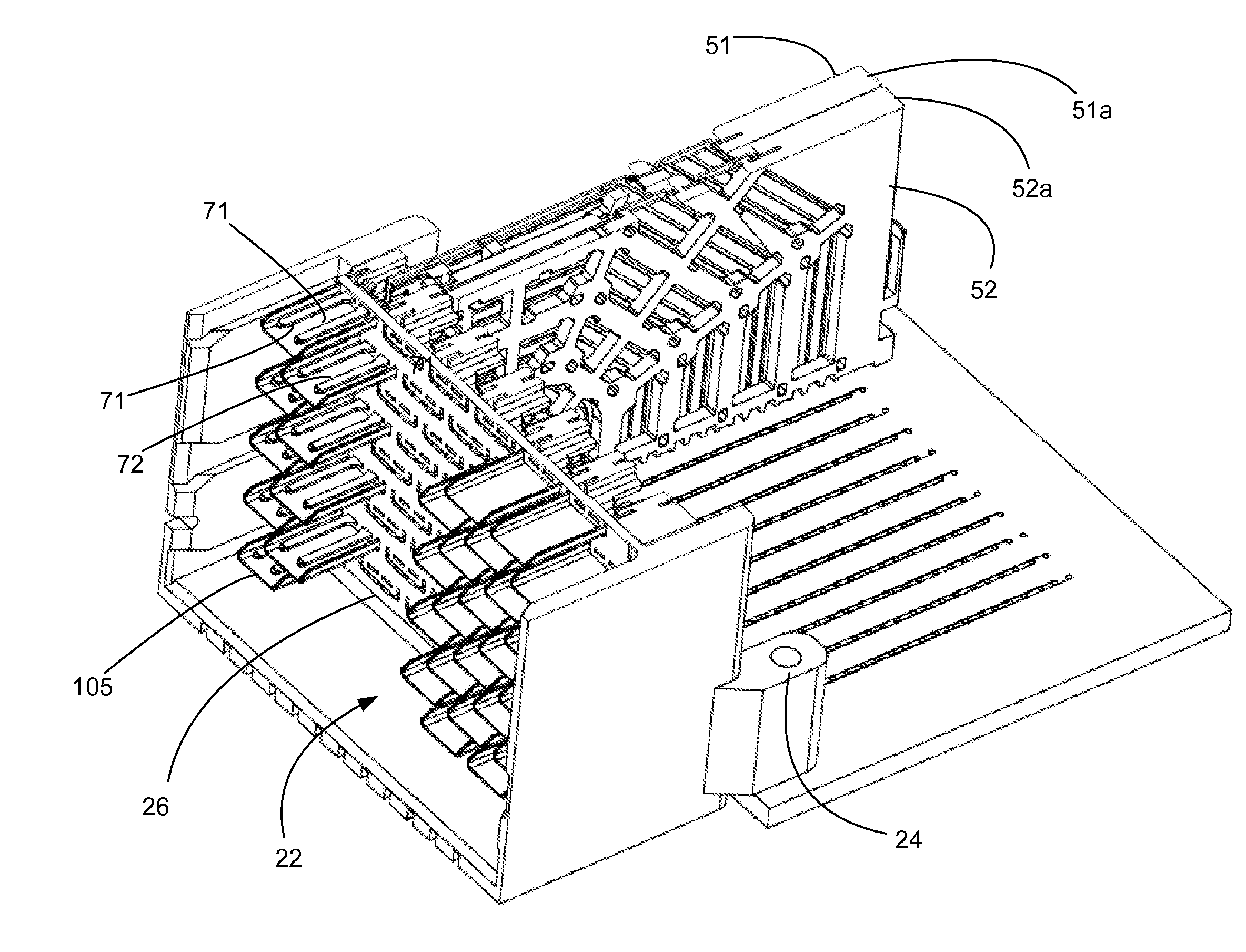
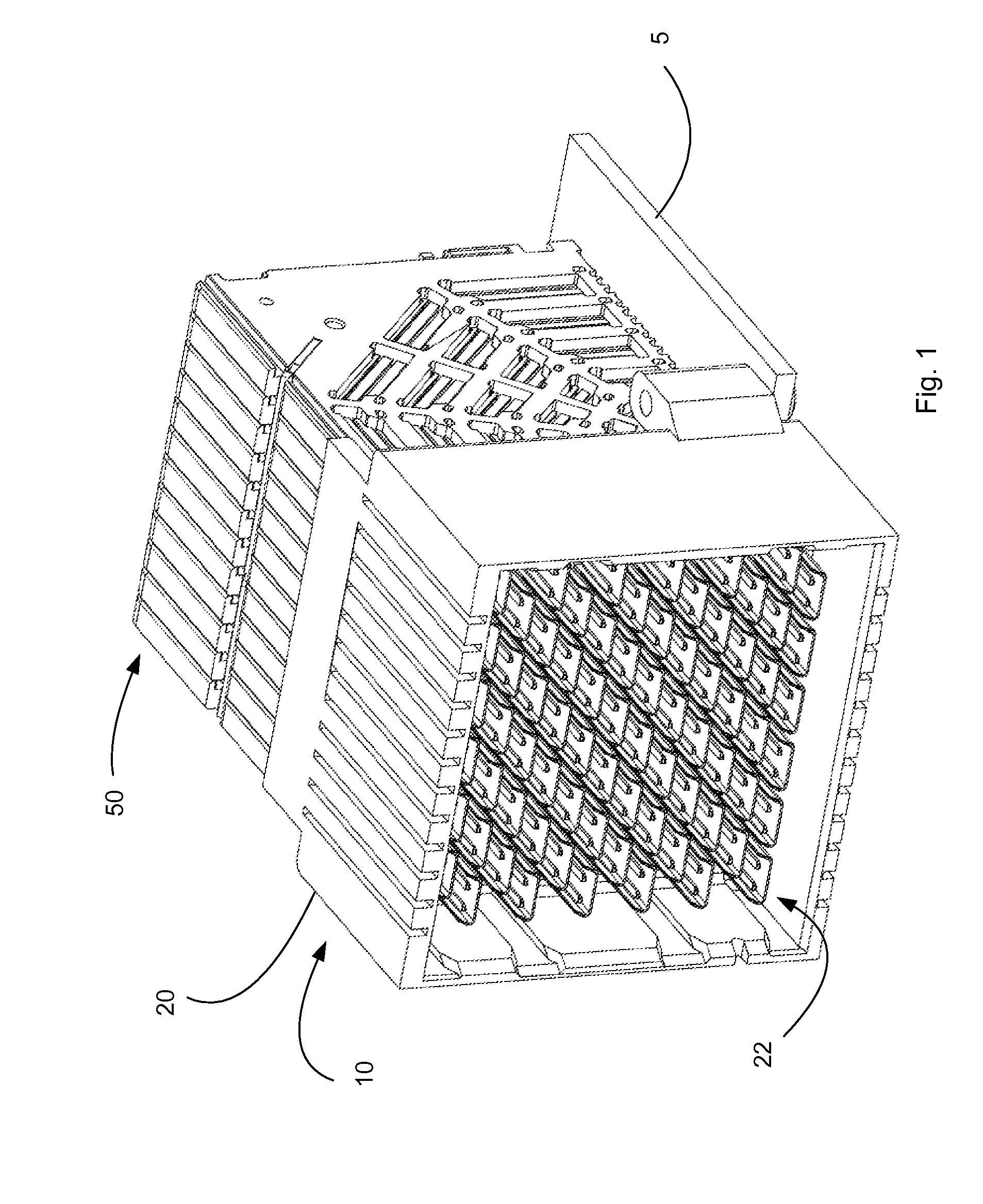
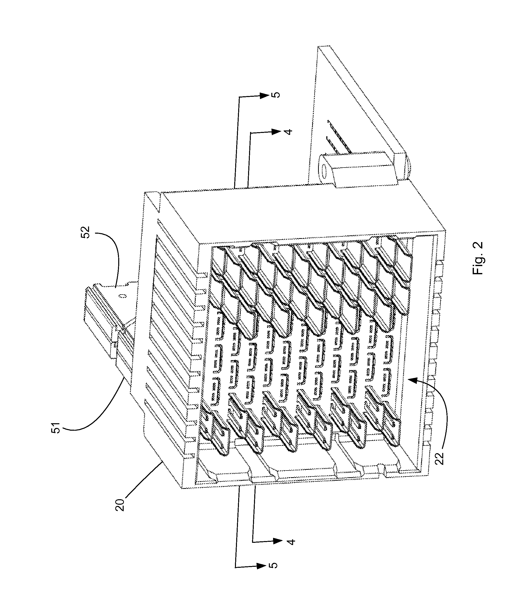
[0036]The specification illustrates a number of features that can be used to provide a connector suitable to enable a direct connection between a daughter card and a main board. One feature that is useful is the 90 degree twist or rotation in alignment provided in mating interface. In the body of the connector, a wafer supports a differential pair in a vertical edge-coupled manner and the bodies of the differential pair are aligned in a first plane while the contacts are still edge coupled but are aligned in a second plane that is orthogonal to the first plane. This provides a beneficial continuation of the edge coupling from a first alignment 121 (e.g., a vertica...


PUM


Abstract

A connector is configured to provide a mating side that includes a 90 degree rotation about two different axis when compared to a mounting. The connector, when mounted on a first circuit board is thus suitable for directly mating to a right-angle connector that is mounted on a second circuit board, the second circuit board at a being at a 90 angle to the first circuit board. The connector can include a shroud that supports a u-shield that partially shields contacts positioned in the mating side.

Description

RELATED APPLICATIONS[0001]This application claims priority to U.S. Provisional Application No. 61 / 857,513, filed Jul. 23, 2013, which is incorporated herein by reference in its entirety.FIELD OF THE INVENTION[0002]The present invention relates to field of connectors that mount on a circuit board, more specifically to a connector suitable for use in a backplane application.DESCRIPTION OF RELATED ART[0003]Connectors suitable for backplanes are often specialized for their environment. Backplane connectors need to have reasonably high density (sometimes referred to as pins per inch) while supporting data channels that have high signaling frequencies. These conflicting requirements make backplane connectors challenging to design, particularly for applications where the channels need to support data rates of 20 Gbps or more (using NRZ encoding).[0004]While a variety of connector configurations are possible, including right angle, mid-plane and mezzanine style connectors, one common applic...

Claims


Application Information

Patent Timeline
Patent Type & Authority Applications(United States)
IPC IPC(8): H01R13/6471H01R13/41H01R13/6587H01R13/514
CPCH01R13/6471H01R13/6587H01R13/41H01R13/514H01R12/737
Inventor LAURX, JOHNSHAH, VIVEK
Owner MOLEX INC
Why Eureka
Try Eureka