
Circuit device

a circuit device and circuit technology, applied in the direction of printed circuits, printed circuit non-printed electric components association, electrical apparatus, etc., can solve the problems of changing the impedance the coil of large size and weight has the disadvantage of being easily damaged, and the magnetic force lines of the coil of the lc resonant circuit can be disturbed, so as to improve the resistance to the impact of the coil

Inactive Publication Date: 2005-10-13
SHARP KK
View PDF3 Cites 1 Cited by
  • Summary
  • Abstract
  • Description
  • Claims
  • Application Information

AI Technical Summary

Benefits of technology

[0013] Moreover, a circuit device in accordance with one or more embodiments of the present invention comprises one or more LC resonant circuits mounted on one or more printed wiring boards and increasing one or more circuit impedances; wherein at least one coil of at least one of the LC resonant circuit or circuits is separated from at least one of the printed wiring board or boards so as to prevent change in at least one impedance of at least one of the LC resonant circuit or circuits.
[0014] Furthermore, in the context of a circuit device comprising one or more LC resonant circuits mounted on one or more printed wiring boards and increasing one or more circuit impedances, and one or more metal chassis for electromagnetically shielding at least a portion of the LC resonant circuit or circuits with respect to the exterior; wherein at least one coil of at least one of the LC resonant circuit or circuits is separated from at least one side wall of at least one of the metal chassis so as to prevent change in at least one impedance of at least one of the LC resonant circuit or circuits.
[0015] Such a constitution makes it possible for lines of magnetic force from coil(s) to be undisturbed by printed wiring board(s) and / or metal chassis side wall(s), inductance(s) of coil(s) to be unchanged, impedance frequency characteristics of LC resonant circuit(s) to be maintained at what they should be, and resonant impedance(s) to not be lowered.
[0017] Because such constitution will permit dielectric body or bodies having elasticity to be captured between or among LC resonant circuit coil(s) and board(s), even where impact(s) is / are exerted on board(s), chassis, and / or the like, such impact(s) can be mitigated by dielectric body or bodies such that impact(s) is / are not directly propagated to coil(s). This permits improved resistance to impact of coil(s).

Problems solved by technology

Furthermore, even where there is only a single LC resonant circuit, lines of magnetic force from the coil of the LC resonant circuit can be disturbed due to the influence of peripheral components; and where this is the case, the inductance of the coil will change, and the impedance of the LC resonant circuit will change.
Such a coil of large size and weight has the disadvantage of being easily damaged, as it will be susceptible to damage upon impact when dropped or the like.

Method used


Image

  • Circuit device
  • Circuit device
  • Circuit device

Examples


first embodiment

[0026] (1) First Embodiment

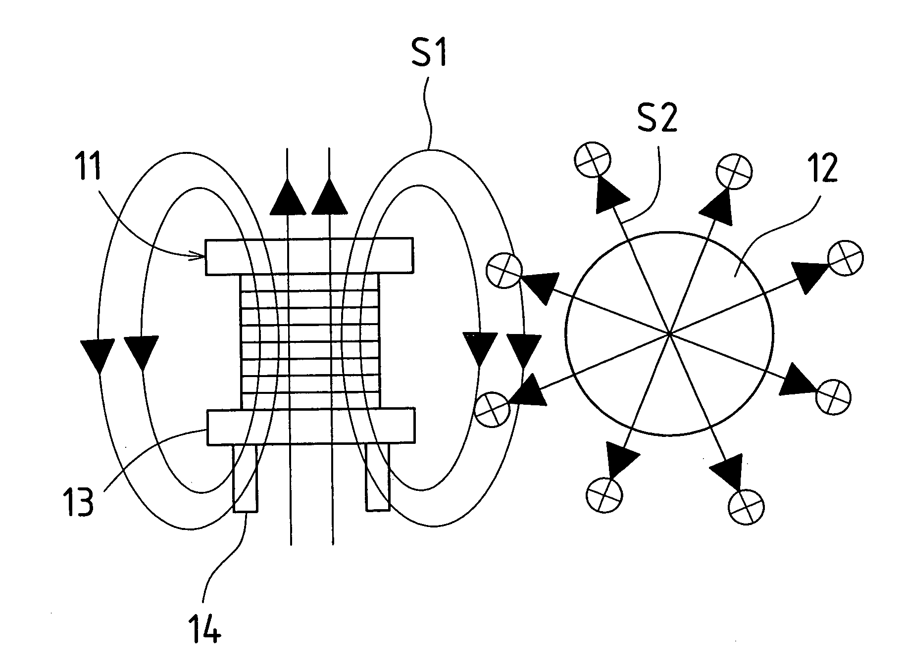
[0027]FIG. 1 is a drawing showing in conceptual fashion a first embodiment of a circuit device in accordance with the present invention. The circuit device of the present embodiment employs first LC resonant circuit(s) and second LC resonant circuit(s) installed therein so as to increase two circuit impedances as seen from circuit input side(s) and / or output side(s).

[0028] This circuit device is equipped with first LC resonant circuit coil(s) 11 and second LC resonant circuit coil(s) 12. At coil 11, wire is wound around drum 13, this wire being connected to respective terminal pins 14 which protrude from the lower end of drum 13. Drum 13 may have either an air core or a magnetic core. The other coil 12 is constructed in similar fashion as coil 11.

[0029] Here, respective coils 11, 12 are oriented such that their centers are mutually perpendicular. For example, coil 11 might be mounted so as to stand upright on the printed wiring board, and coil 12 might b...

second embodiment

[0031] (2) Second Embodiment

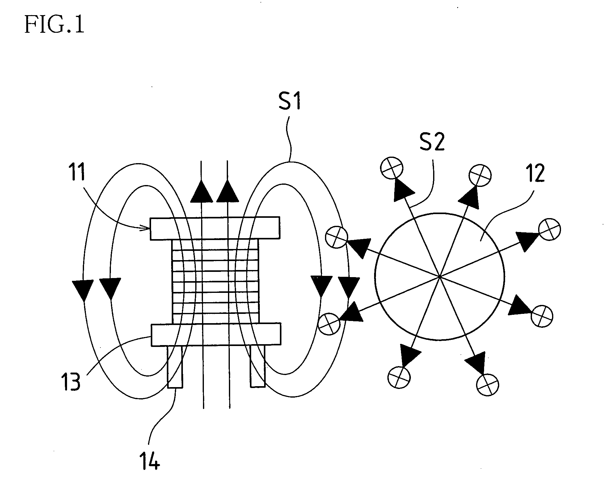
[0032]FIG. 2 is a side view showing a second embodiment of a circuit device in accordance with the present invention. The circuit device of the present embodiment employs first LC resonant circuit(s), second LC resonant circuit(s), and third LC resonant circuit(s) installed therein so as to increase three circuit impedances.

[0033] This circuit device is equipped with first LC resonant circuit coil(s) 21, second LC resonant circuit coil(s) 22, third LC resonant circuit coil(s) 23, and printed wiring board(s) 24 on which respective coils 21, 22, 23 are mounted. At coil 21, wire is wound around drum 25, this wire being connected to respective terminal pins 26 which protrude from the lower end of drum 25. Drum 25 may have either an air core or a magnetic core. The other respective coils 22, 23 are constructed in similar fashion as coil 21.

[0034] Here, respective coils 21, 22, 23 are respectively mounted at the front and back sides of printed wiring board 24...

third embodiment

[0036] (3) Third Embodiment

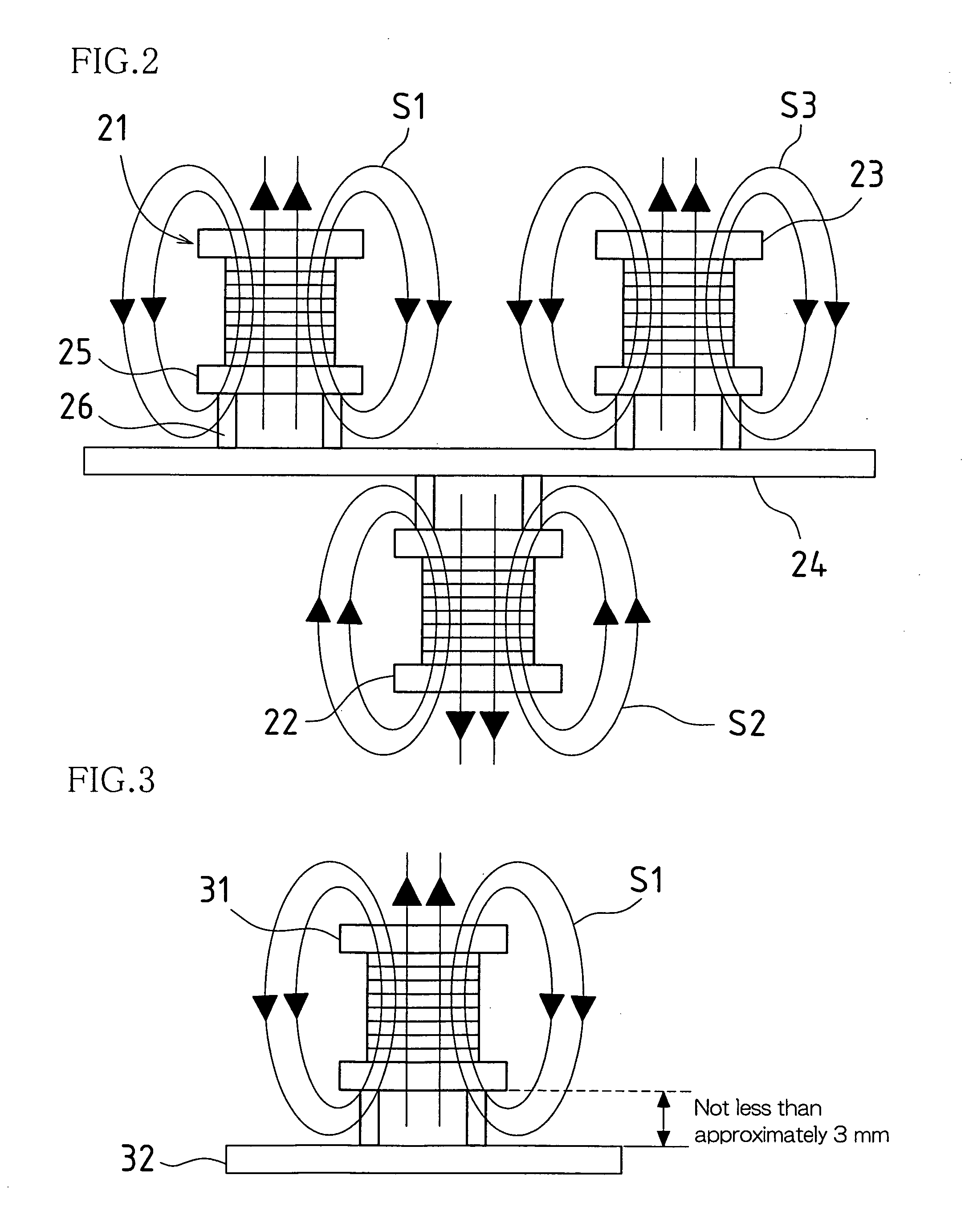
[0037]FIG. 3 is a side view showing a third embodiment of a circuit device in accordance with the present invention. As shown in FIG. 3, in the circuit device of the present embodiment, coil 31 of an LC resonant circuit installed therein so as to increase circuit impedance is separated from printed wiring board 32 by not less than 3 mm.

[0038] Because a variety of components are mounted on printed wiring board 32, it is possible that same will include magnetic material(s) thereamong. This being the case, if coil 31 were to be brought close to printed wiring board 32, lines of magnetic force SI from coil 31 could be disturbed by magnetic material(s) at printed wiring board 32, changing the inductance of coil 31 and changing the impedance of the LC resonant circuit.

[0039] But where, as in the present embodiment, coil 31 is separated from printed wiring board 32 by not less than 3 mm, lines of magnetic force SI from coil 31 will not be disturbed by magnetic ...


PUM


Abstract

Coil(s) 11 and coil(s) 12 of LC resonant circuit(s) are oriented such that their centers are mutually perpendicular. For example, coil 11 might be mounted so as to stand upright on printed wiring board, and coil 12 might be mounted so as to lie flush against printed wiring board. Such configuration permitting lines of magnetic force from coil 11 and coil 12 to be oriented so as to be mutually perpendicular, lines of magnetic force from coil 11 and coil 12 do not merge, and coil 11 and coil 12 are not electromagnetically coupled. Accordingly, inductances of respective coils 11, 12 are unchanged; impedance frequency characteristics of respective LC resonant circuits are maintained at what they should be; and resonant impedance(s) is / are not lowered.

Description

BACKGROUND OF INVENTION [0001] This application claims priority under 35 U.S.C. § 119(a) to Patent Application No. 2004-049802 filed in Japan on 25 Feb. 2004, the content of which is hereby incorporated herein by reference in its entirety. [0002] The present invention relates to a circuit device comprising LC resonant circuit(s) that increase circuit impedance(s). [0003] Such circuit devices employ LC resonant circuit(s) so as to increase circuit impedance(s) as seen from the input side and / or the output side of the circuit. [0004] For example, as shown in FIG. 6, LC resonant circuit 103, in which coil 101 and capacitor 102 are connected in parallel, might be inserted between input terminal 104 and low-impedance circuit 105, and the resonant frequency of LC resonant circuit 103 might be made to agree with the frequency of a pulsed signal which is input thereto from input terminal 104. Upon input of a pulsed signal from input terminal 104, LC resonant circuit 103 resonates, displayin...

Claims


Application Information

Patent Timeline
Patent Type & Authority Applications(United States)
IPC IPC(8): H03H7/38H05K1/18H03H7/01H03H5/12H03H5/02
CPCH03H7/38H05K1/18H05K2201/1003H05K2201/10545
Inventor OKAHASHI, TETSUHIDE
Owner SHARP KK
Learn More