
Current-based RF driver for pulsed electromagnetic field applicator systems

a pulsed electromagnetic field and driver technology, applied in the field of current-based rf driver for pulsed electromagnetic field applicator systems, can solve the problems of reducing the wound healing time of chronic pressure ulcers, surgical wounds, and the cost of apparatuses, and achieve the effect of reducing the electrical field signal

Pending Publication Date: 2021-04-29
REGENESIS BIOMEDICAL
View PDF3 Cites 0 Cited by
  • Summary
  • Abstract
  • Description
  • Claims
  • Application Information

AI Technical Summary

Benefits of technology

The patent describes a way to make PEMF (pulsed electromagnetic field) treatment more efficient and easier to use. The invention is based on the use of single RF (radio frequency)-based drivers to transmit controlled currents, which can be measured at the driver to simplify the apparatus. The invention also regulates the application of the magnetic field or the ratio of the magnetic field to the electric field to provide better outcomes. The use of current rather than voltage simplifies the apparatus, as it reduces or eliminates the need for feedback sensors. The apparatus includes an electrostatic shield to prevent capacitance changes and ensure maximum power transfer to the applicator. The invention does not require a sensor to control the magnetic field, as it maintains a constant magnetic field. Overall, the invention simplifies and enhances PEMF treatment.

Problems solved by technology

Moreover, published reports of double blind placebo-controlled clinical trials utilizing a RF transmission device (Diapulse) suggest that this ancillary treatment device significantly reduces wound healing time for chronic pressure ulcers as well as for surgical wounds.
This, amongst other reasons, may make the apparatuses expensive, and in some variations, heavy.

Method used


Image

  • Current-based RF driver for pulsed electromagnetic field applicator systems
  • Current-based RF driver for pulsed electromagnetic field applicator systems
  • Current-based RF driver for pulsed electromagnetic field applicator systems

Examples


Embodiment Construction

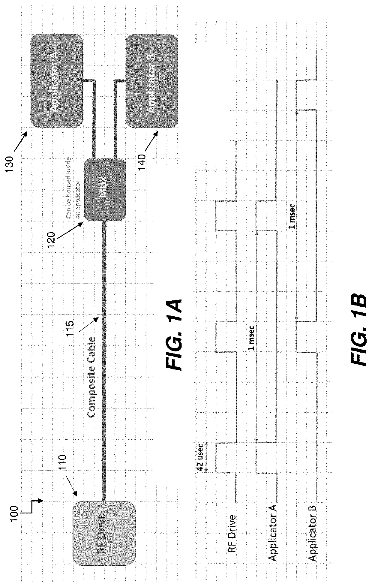
[0048]Current apparatuses in the field of EM treatment generally uses an energy source (e.g., a RF Driver) for each applicator in the system. Building and assembly of the multiple RF drive boards introduces inconsistencies in the radiated treatment fields emitted from these applicators. This also increases cost and size of the systems. Additionally, the typical multiplicity of cabling in the commercially available apparatuses is awkward to use. Therefore, there is a need in the field for improved PEMF applicator apparatuses for more compliant and convenient use, reducing complexity and weight and increasing the margin of safety of the energetics.

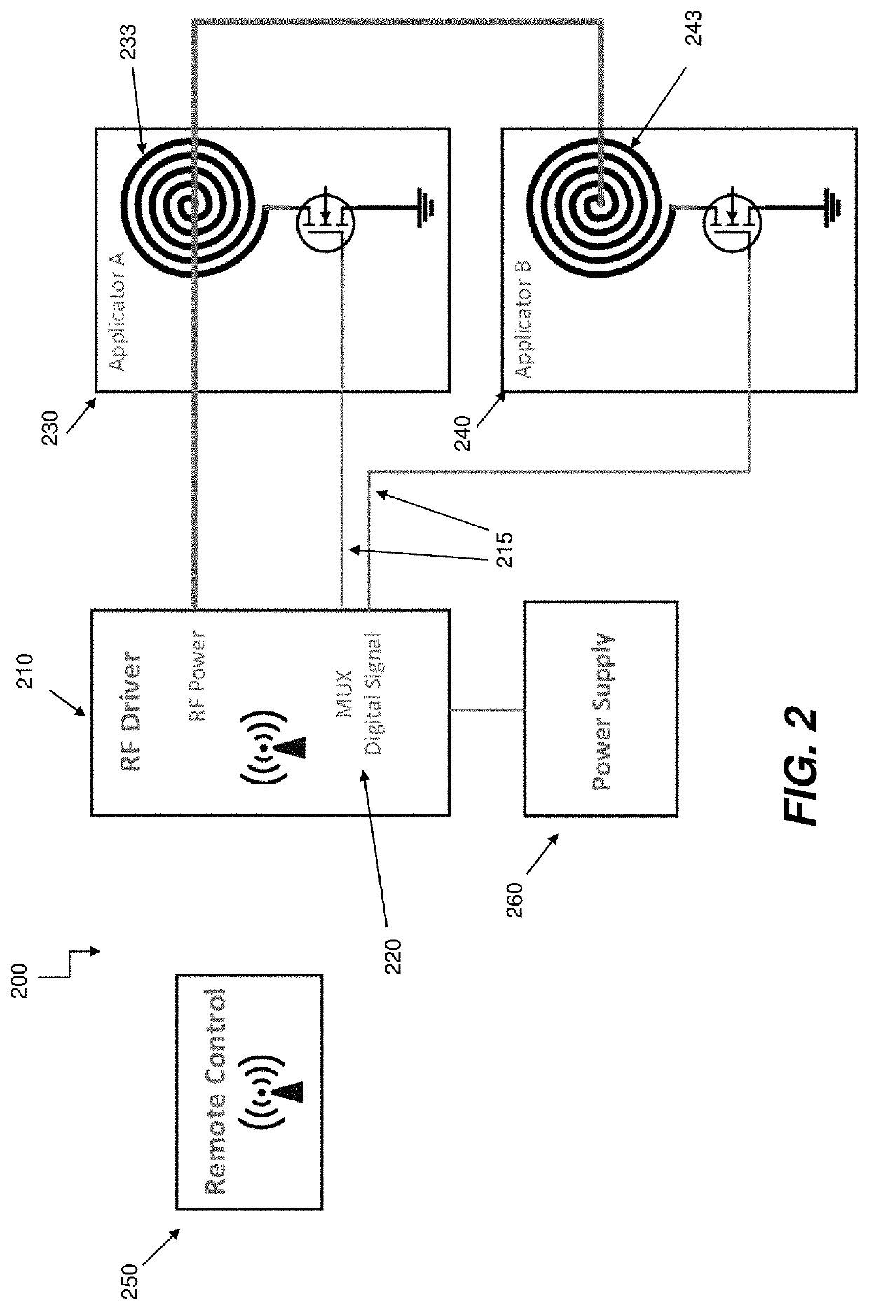
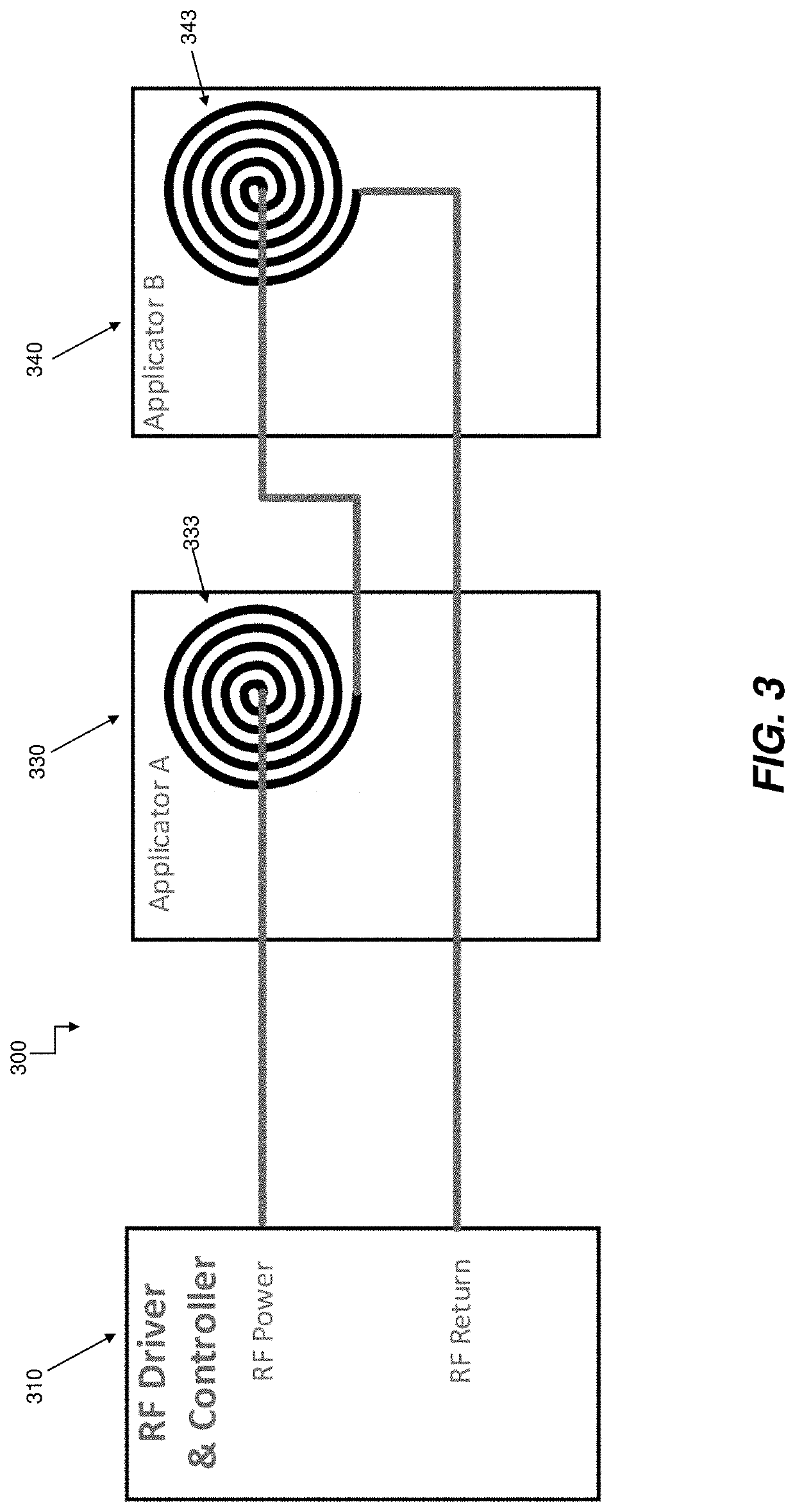
[0049]Apparatuses are described herein that reduce the number of energy Drives to only one current-driven Driver (which may be a RF Driver, but the apparatus is not so limited), regardless of the number of treatment applicators, which may be one or more applicators. The apparatuses thus configured can more simply control the electronics to p...


PUM


Abstract

The apparatuses can comprise a controller including a RF driver configured to generate a pulsed current signal and one or more applicators coupled to the controller. Each applicator can include a coil circuit configured to receive the pulsed current signal and to emit a pulsed electromagnetic field signal comprising a magnetic field signal.

Description

CROSS REFERENCE TO RELATED APPLICATIONS[0001]This application claims the benefit of U.S. Provisional Patent Application No. 62 / 926,375, filed Oct. 25, 2019, titled “CURRENT-BASED RF DRIVER FOR PULSED ELECTROMAGNETIC FIELD APPLICATOR SYSTEMS,” which is herein incorporated by reference in its entirety.[0002]The following U.S. patent applications are herein incorporated by reference in their entirety to the same extent as if each individual publication or patent application was specifically and individually indicated to be incorporated by reference: U.S. Pat. No. 6,334,069, titled “PULSED ELECTROMAGNETIC ENERGY TREATMENT APPARATUS AND METHOD”, filed on Jan. 15, 1999, U.S. Pat. No. 6,353,763, titled “PULSED ELECTROMAGNETIC ENERGY TREATMENT APPARATUS AND METHOD”, filed on Jun. 27, 2000, U.S. Pat. No. 6,967,281, titled “COVER FOR ELECTROMAGNETIC TREATMENT APPLICATOR”, filed on Oct. 22, 2003, U.S. Pat. No. 6,974,961, titled “COVER FOR ELECTROMAGNETIC TREATMENT APPLICATOR”, filed on Sep. 14...

Claims


Application Information

Patent Timeline
IPC IPC(8): A61N2/02G06K7/10
CPCA61N2/02G06K7/10366
Inventor BABICO, JOHN Y.
Owner REGENESIS BIOMEDICAL
Learn More