Tailstock for machine tools

a technology for machine tools and tailstocks, which is applied in the direction of tailstocks/centres, turning machine accessories, manufacturing tools, etc., can solve the problems of increasing the clamping force of the tailstock, the one-piece piston design of the tailstock for each lateral side of the tailstock is believed to no longer meet the requirement of an upgraded clamping force, and it is almost impossible to upgrade the tailstock to meet the need of increasing the clamping force for holding the workpiece. ,

Active Publication Date: 2016-06-30
TAIWAN TAKISAWA TECH
View PDF9 Cites 1 Cited by
  • Summary
  • Abstract
  • Description
  • Claims
  • Application Information

AI Technical Summary

Benefits of technology

[0007]Accordingly, it is the primary object of the present invention to provide a tailstock for machine tools, especially for the lathes, that is a multi-stage piston design and can increase the whole clamping force of the tailstock without an additional increase of the installation space or change of the appearance thereof by introducing a specific arrangement of components within the limited space inside the tailstock.

Problems solved by technology

However, as the dimension of the work piece to be machined by the lathe increases, the weight of the work piece as well as the load in the lathe becomes heavier.
In the art, the one-piece piston design for each lateral side of the tailstock is believed no longer to meet the requirement of an upgraded clamping force.
However, in the circumstance of the limited space available around the lathe tailstock, it is almost impossible to upgrade the tailstock for meeting the need of increasing clamping force for holding the work piece.

Method used


Image

  • Tailstock for machine tools
  • Tailstock for machine tools
  • Tailstock for machine tools

Examples


Embodiment Construction

[0022]The invention disclosed herein is directed to a tailstock for machine tools. In the following description, numerous details are set forth in order to provide a thorough understanding of the present invention. It will be appreciated by one skilled in the art that variations of these specific details are possible while still achieving the results of the present invention. In other instance, well-known components are not described in detail in order not to unnecessarily obscure the present invention.

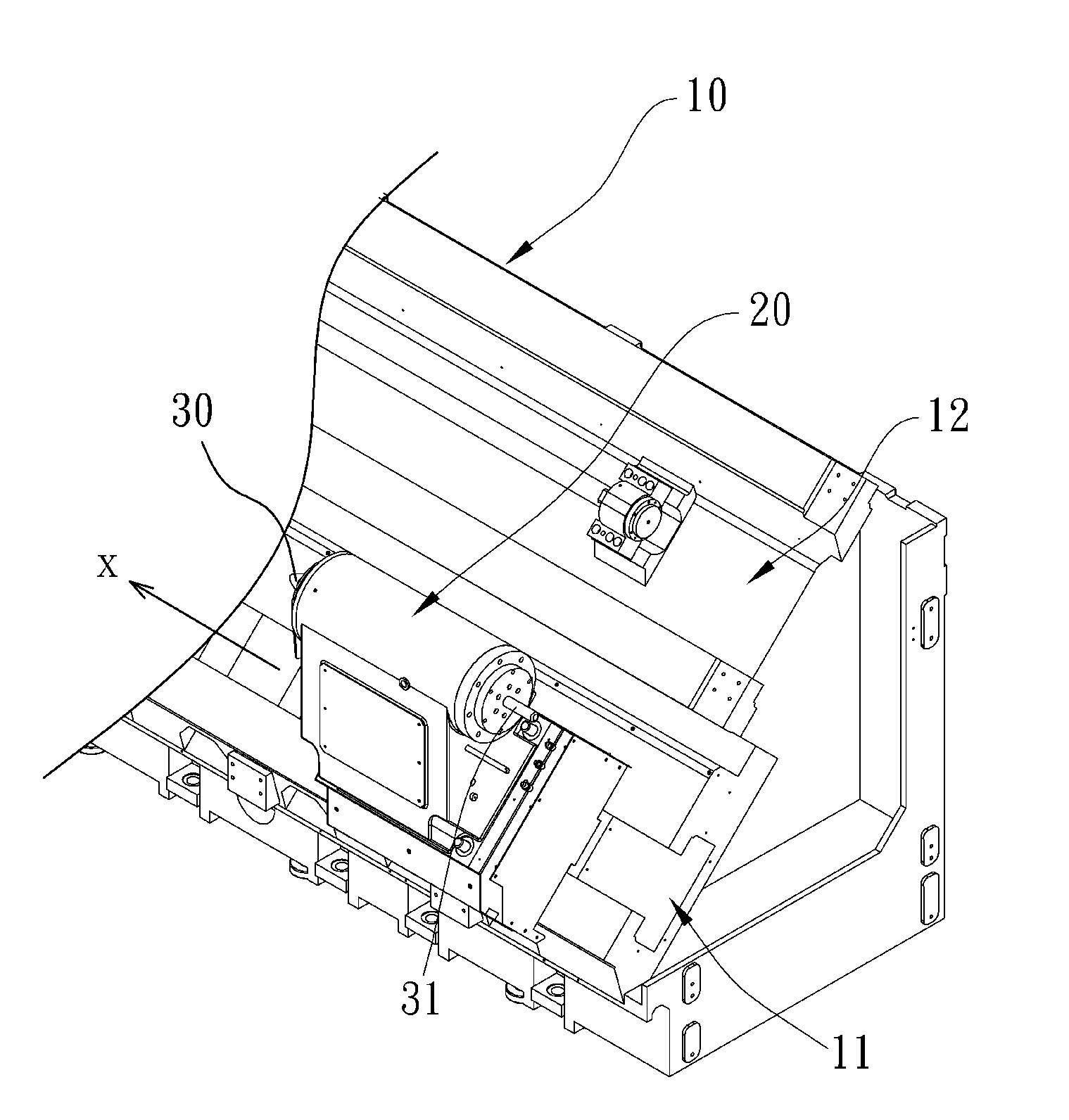
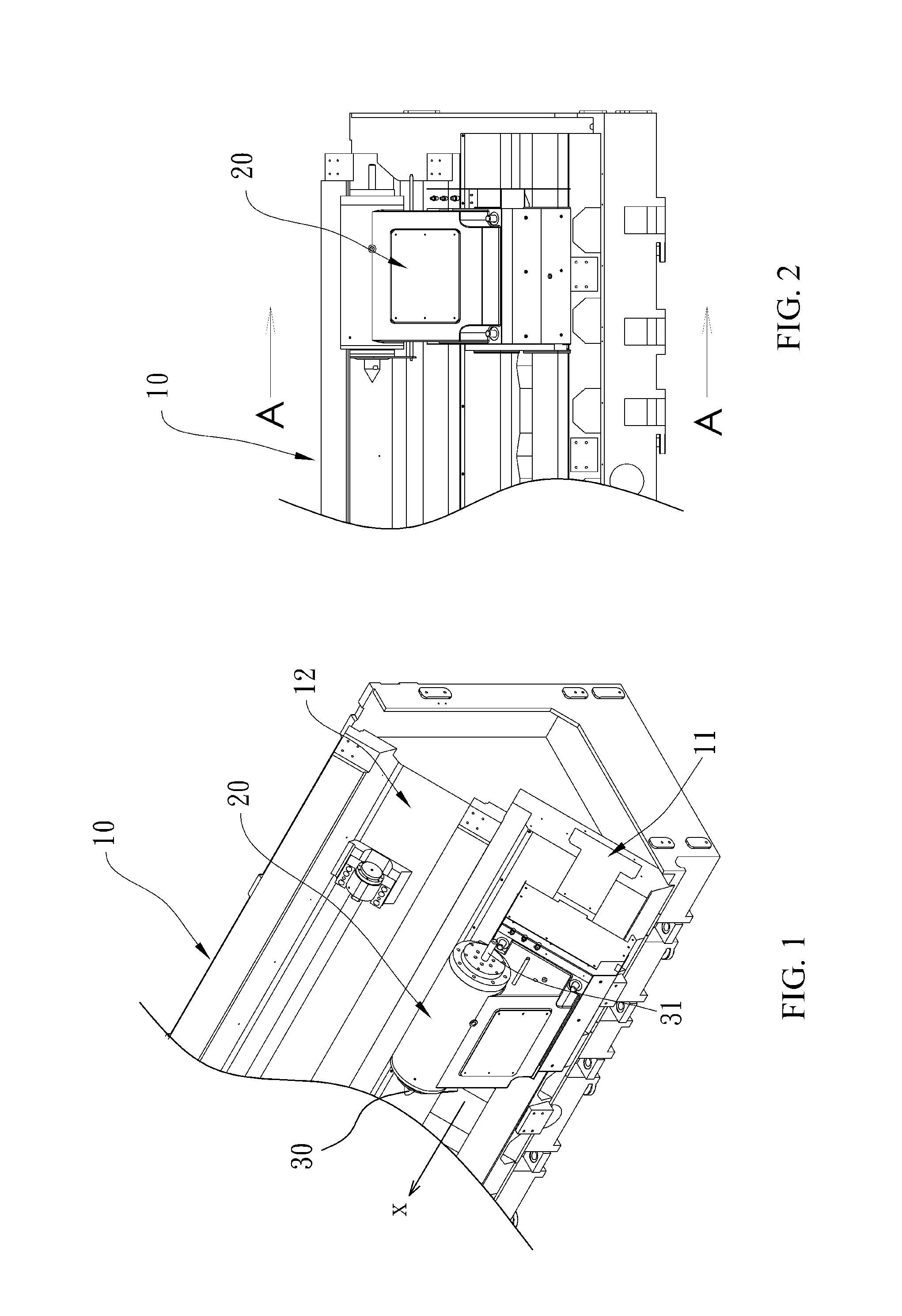
[0023]Referring now to FIG. 1 and FIG. 2, the preferred tailstock 20 of the present invention is shown to be mounted at a specific part of the lathe. An oblique surface 12 is shown to be located between a top surface 12 and a bottom surface of the main frame 10 of the lathe, and a slide rail 11 is longitudinally extended toward opposing lateral sides of the main frame 10 along a direction of the oblique surface 12. The lateral sides of the lathe (also, the main frame 10) are defined w...


PUM

PropertyMeasurementUnit
angleaaaaaaaaaa
angleaaaaaaaaaa
clamping forceaaaaaaaaaa

Abstract

A tailstock includes a main body, a lathe center unit arranged in a hollow hole of the main body, a sliding base coupled with the main body and having a slider configured at a side thereof for pairing a slide rail, and a clamping unit configured in the sliding base. The clamping unit for increasing clamping force of the tailstock further includes a connection plate having at least one positioning hole to connect the main body, at least one hydraulic rod bridging the slider and the main body, a plurality of loading devices ring-set about the hydraulic rod, and a plurality of sleeves ring-set with the corresponding loading devices.

Description

[0001]This application claims the benefit of Taiwan Patent Application Serial No. 103223309, filed Dec. 30, 2014, the subject matter of which is incorporated herein by reference.BACKGROUND OF INVENTION[0002]1. Field of the Invention[0003]The invention relates to a tailstock for machine tools, and more particularly to the tailstock for lathes that provide a clamping unit to increase the clamping force of a tail hydraulic tank of the lathe.[0004]2. Description of the Prior Art[0005]The conventional lathe is a machine tool that is specified in machining longitudinal work pieces with a round cross section. While in applying lathe to machine a work piece, one end of the work piece is fixed to a rotational spindle, while another end thereof is connected with a tailstock. Generally, the tailstock has a main body mounted fixedly to a station frame of the lathe. The main body may be equipped with a protruding lathe center for point-contacting the work piece so as to align the central line of...

Claims


Application Information

Patent Timeline
Patent Type & Authority Applications(United States)
IPC IPC(8): B23B23/00
CPCB23B2270/025B23B23/00B23Q1/28
Inventor LIU, CHUN-I
Owner TAIWAN TAKISAWA TECH
Why Eureka
Try Eureka