Airfoil masking tool and method of polishing an airfoil

Active Publication Date: 2016-06-30
MDS COATING TECH
View PDF8 Cites 3 Cited by
  • Summary
  • Abstract
  • Description
  • Claims
  • Application Information

AI Technical Summary

Benefits of technology

The invention is about a way to make things shine too well. The goal is to avoid causing damage to parts, like turbine blades, that need to be perfectly matched.

Problems solved by technology

However, the high energy nature of these processes can result in the loss of material at sharp edges which may harm the dimensions of the part.
When it comes to polishing close-toleranced parts such as gas turbine engine airfoils, the polishing process can be very aggressive on sharp radius edges and corners such as the leading and trailing edges of the airfoils and blade tip corners.
Changes in the dimensions of the leading and trailing edges and blade tip corners can have a profoundly detrimental effect on the mechanical properties and aerodynamic efficiency of the airfoils.

Method used


Image

  • Airfoil masking tool and method of polishing an airfoil
  • Airfoil masking tool and method of polishing an airfoil
  • Airfoil masking tool and method of polishing an airfoil

Examples


example 1

1. Tumbling Machine

[0055]The example of the tumbling machine used in this embodiment of the process was a Walter Trowal MV-25

2. Ceramic Media

[0056]The ceramic media used in this process can be almost any media that is suitable for contacting all areas of the part to be polished. One embodiment of this process used Rosier RCP porcelain non-abrasive polishing stones to process the parts.

3. An Abrasive Paste

[0057]The abrasive used in this process comprises:

[0058]2.5 Kg Rosler paste (RPP6279), or Rosler RPP579, or Walther Trowel SDB Trowapast PKP

[0059]5 L water

[0060]And was a suitable quantity to use with 800-900 lbs Rosier RCP media.

4. Stationary Fixed Parts

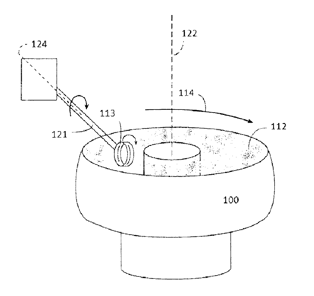
[0061]Airfoils protected with masking tooling similar to that described here were mounted on a base plate and loaded into the tumbling machine and were held stationary on a plate in the tumbler as shown in FIG. 3.

[0062]The Walter Trowal MV-25 tumbling machine is equipped with three vibrator motors; two on the side and one on the bas...

example 2

[0065]The same process as Example 1 was used to super polish airfoils that were first coated with an erosion resistant coating, MDS Coating Technologies' BlackGold® coating. The erosion resistant coating was applied to the airfoils and once polished according to the present invention to a surface finish (Ra) of less than 4 μin. The surface finish retention of the coated and polished surface was compared to an uncoated surface having a surface finish (Ra) of less than 4 μin by subjecting the polished coated and uncoated surfaces to erosion using Arizona road dust as the abrasive media. FIG. 7 illustrates the results of the erosion test. The results shown in FIG. 7 demonstrate that the polished coating prolonged and maintained the surface finish in erosive conditions to an Ra of less than 10 μin. In contrast, the uncoated polished surface at the same conditions resulted in a surface finish Ra of 34 μin. The erosion test procedure is shown schematically in FIG. 8.

[0066]The abrasive pas...


PUM

PropertyMeasurementUnit
Weightaaaaaaaaaa
Weightaaaaaaaaaa
Angleaaaaaaaaaa

Abstract

An airfoil masking tool constructed to protect the leading edge, trailing edge and tip of an airfoil during polishing of the airfoil. A method of polishing an airfoil using the masking tool.

Description

[0001]This application claims priority to U.S. provisional patent application Ser. Nos. 61 / 870,980, filed 28 Aug. 2013; 61 / 907,207, filed 21 Nov. 2013; 61 / 913,439, filed 9 Dec. 2013; and 62 / 001,425, filed 21 May 2014, the complete disclosures of which are incorporated herein by reference.FIELD OF THE INVENTION[0002]The invention relates to an airfoil masking tool and use of the masking tool in a method of polishing the airfoil.BACKGROUND OF THE INVENTION[0003]The demand for ever greater efficiency gains in gas turbine engines has lead to the demand for ultra-fine (low surface roughness) airfoils that have a surface roughness Ra in the region of 1 to 5 micro-inches. NASA has demonstrated that an industry-standard surface finished compressor rotor blade ultrapolished, also known by super finishing, super polishing, ultra finishing and high precision surface finishing, to a 5 micro-inch finish can produce an increase in engine efficiency of approximately 0.5%, William B. Roberts et al,...

Claims


Application Information

Patent Timeline
IPC IPC(8): B24B31/00B24B31/12B24B31/10
CPCB24B31/003B24B31/12B24B31/10B24B31/06
Inventor MARTIN, LEEBELL, JOSHUA
Owner MDS COATING TECH
Why Eureka
Try Eureka