Cutter and Printer

a printer and cutter technology, applied in the field of cutters and printers, can solve the problems of shortened cutting period, still wear and chatter of the blades, and media may not be desirably cut, and achieve the effect of preventing wear and chatter

Active Publication Date: 2016-06-30
SEIKO EPSON CORP
View PDF2 Cites 15 Cited by
  • Summary
  • Abstract
  • Description
  • Claims
  • Application Information

AI Technical Summary

Benefits of technology

[0006]A cutter and a printer having the cutter of the invention preve...

Problems solved by technology

If the space of no contact between the cutter blades on the return path is too short, there is still wear and chatter from the blades rubbing against each other after the medium is cut.
Furthermore, if the second cutter blade is set to the contact positio...

Method used


Image

  • Cutter and Printer
  • Cutter and Printer
  • Cutter and Printer

Examples


Embodiment Construction

[0027]A preferred embodiment of a printer according to the present invention is described below with reference to the accompanying figures.

General Configuration

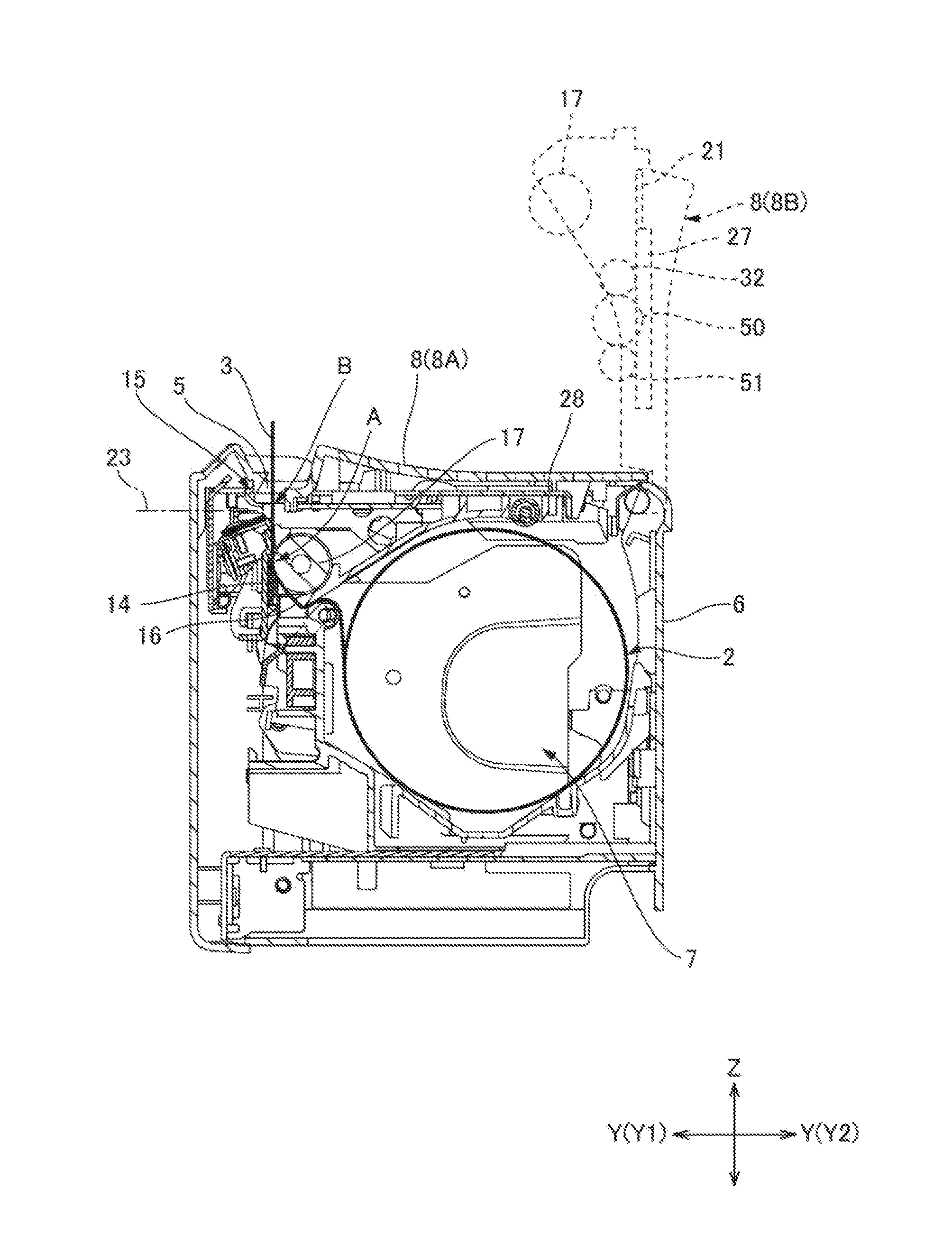
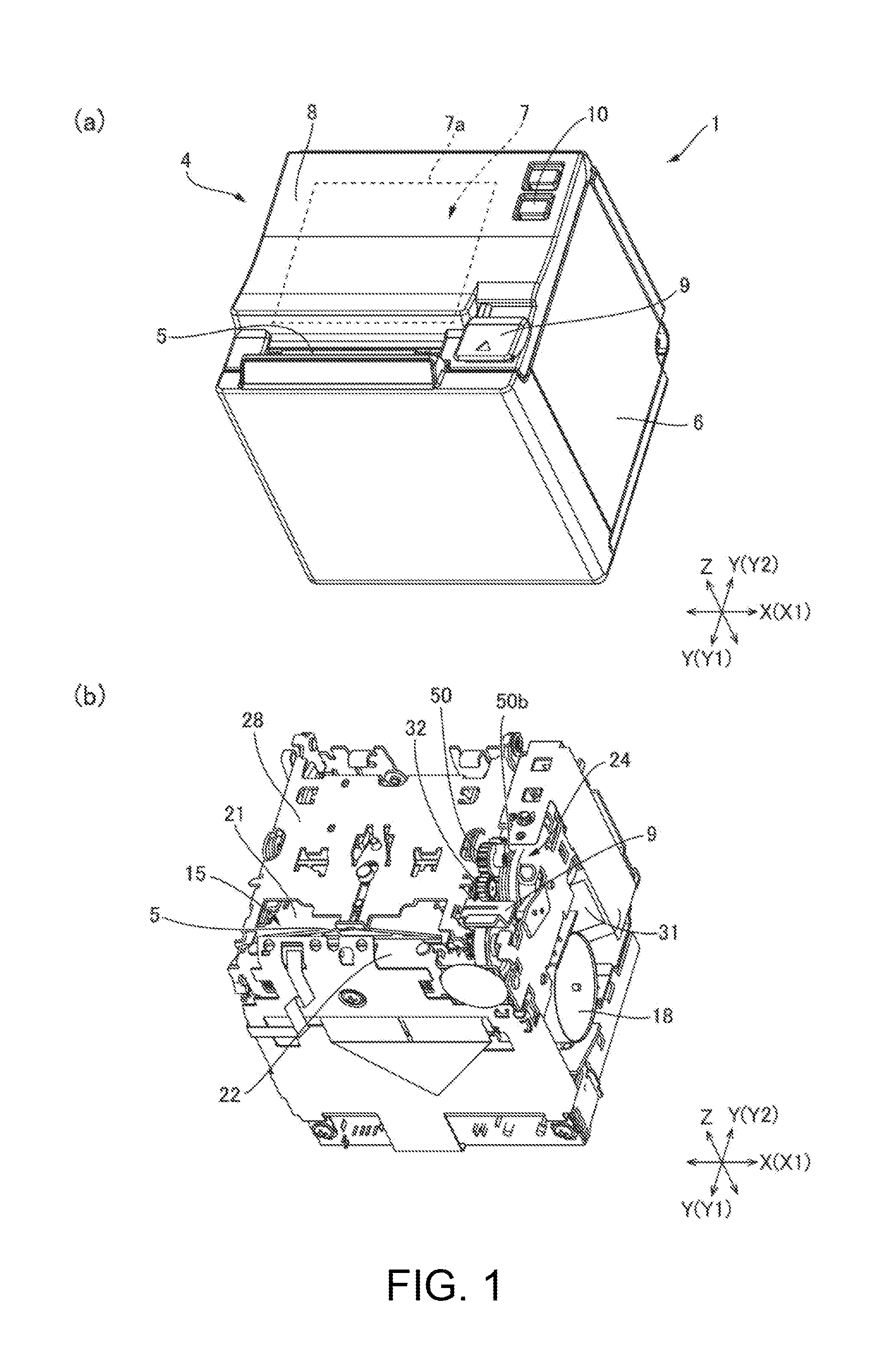
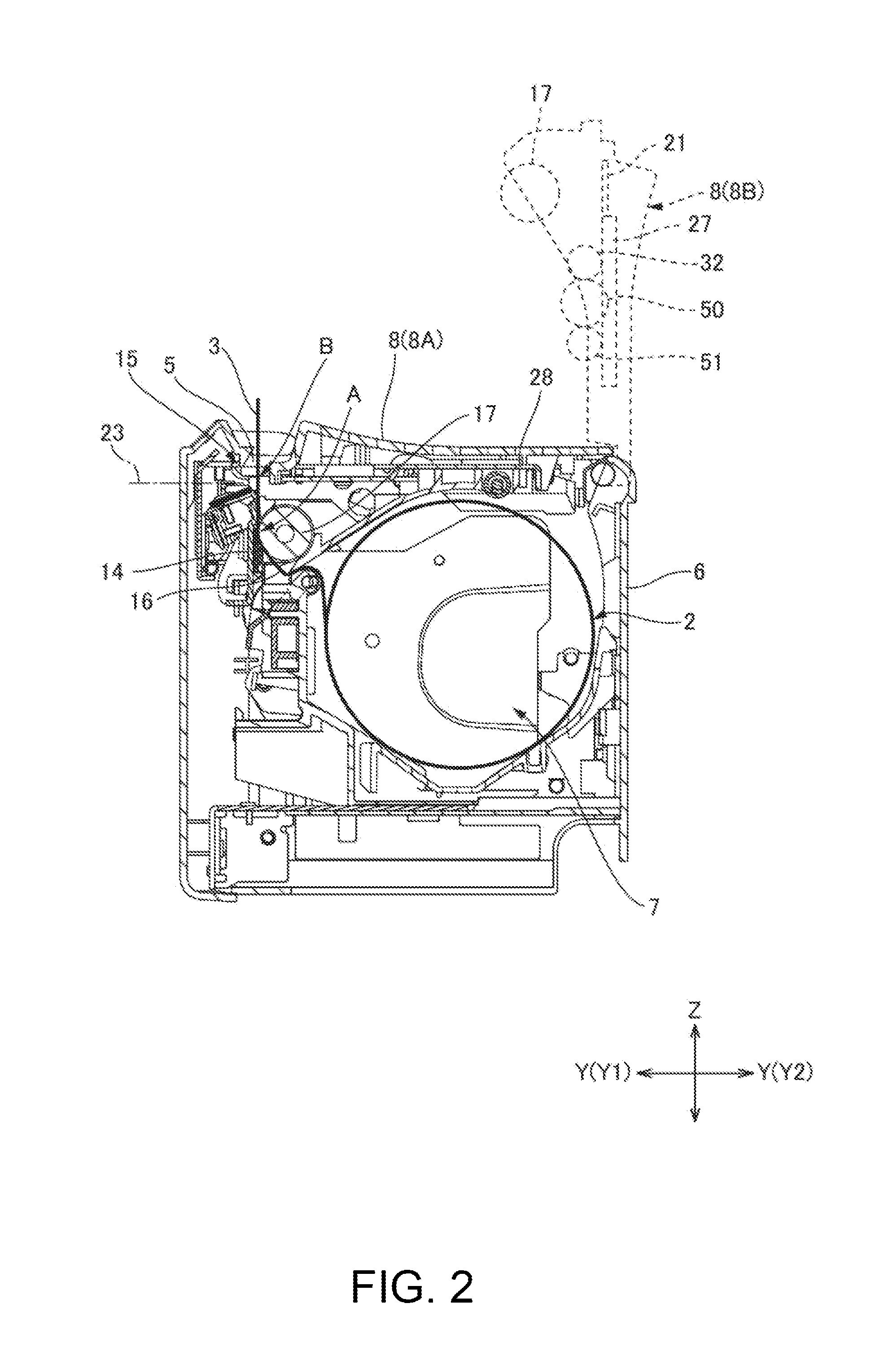
[0028]FIG. 1, view (a) is an oblique view of a printer 1 according to an embodiment of the invention, and FIG. 1, view (b) is an oblique view of the printer 1 in view (a) without the outside case 4. FIG. 2 is a section view of the printer 1 in FIG. 1. The printer 1 in this example is a roll paper printer that prints on recording paper 3 delivered from a paper roll 2. As shown in FIG. 1, the printer 1 has a basically box-like printer case 4. A paper exit 5 from which the recording paper 3 is discharged is formed in the top front part of the printer case 4. The paper exit 5 extends widthwise to the printer 1. Note that three mutually perpendicular axes, a transverse axis X aligned with the printer width, a longitudinal axis Y, and a vertical axis Z, are used below.

[0029]The printer case 4 includes a box-like main case 6, and an...


PUM


Abstract

A cutter has a first cutter blade moving mechanism 24 that moves a first cutter blade 21 reciprocally between a forward position 21A where recording paper 3 is cut and a retracted position 21B separated from the forward position 21A; and a second cutter blade moving mechanism 25 that moves a second-cutter blade 22 between a contact position 22A where the paper is cut in contact with the first-cutter blade 21 and a release position 22B separated from the contact position. The second cutter blade moving mechanism 25 sets the second cutter blade 22 to the release position 22B before the first cutter blade moving mechanism 24 moves the first cutter blade 21 from the forward position 21A to the retracted position 21B. Wear and noise can be prevented because the two cutter blades 21, 22 do not contact after cutting the recording paper 3.

Description

BACKGROUND[0001]1. Technical Field[0002]The present invention relates to a cutter for cutting sheet media by moving a first cutter blade and a second cutter blade against each other, and to a printer having the cutter.[0003]2. Related Art[0004]JP-A-H5-318385 describes a cutter of the related art. In JP-A-H5-318385, a first cutter blade moves reciprocally between a forward position where the medium is cut, and a retracted position removed from the forward position. The second cutter blade is disposed to a cutting position where the first cutter blade slides against the second cutter blade on the outbound path of the first cutter blade as it moves from the retracted position to the forward position. The second cutter blade is also disposed to a separation position where the second cutter blade separates from the first cutter blade on the return path of the first cutter blade returning from the forward position to the retracted position. Because the contact period of the first cutter b...

Claims


Application Information

Patent Timeline
IPC IPC(8): B41J11/70B26D5/08B26D1/06
CPCB41J11/70B26D1/065B26D5/083B26D1/151B26D1/16B26D5/08B41J11/66B41J11/663B41J11/706
Inventor ISHIDA, TETSUGONISHIJIMA, HIDEAKI
Owner SEIKO EPSON CORP
Why Eureka
Try Eureka