Chest drainage systems and methods

a drainage system and chest technology, applied in the field of chest drainage system, can solve the problems of high values of momentary negativity on the patient, and achieve the effect of enhancing the removal of any loculated fluid

Active Publication Date: 2016-07-07
ATRIUM MEDICAL
View PDF2 Cites 11 Cited by
  • Summary
  • Abstract
  • Description
  • Claims
  • Application Information

AI Technical Summary

Benefits of technology

[0058]In another embodiment, in the chest drainage system of any of the previous embodiments, the pressure of the fluid pathway is managed to enhance removal of any loculated fluid from the pleural space of the patient by intermittently changing the pressure applied to the pleural space.
[0059]In another embodiment, in the chest drainage system of any of the previous embodiments, the system is configured to enhance removal of any loculated fluid from the pleural space of the patient by intermittently changing pressure applied to the pleural space to sub-atmospheric pressure values that are outside of a target range of sub-atmospheric pressure values.

Problems solved by technology

However, continuous bubbling through the liquid indicates either an air leak in the connections or an air leak in the pleural cavity of the patient.
In order to clear a blockage, the attendant “milks” the tube in an attempt to reopen it, however, this procedure often causes high values of momentary negativity on the patient.

Method used


Image

  • Chest drainage systems and methods
  • Chest drainage systems and methods
  • Chest drainage systems and methods

Examples


Embodiment Construction

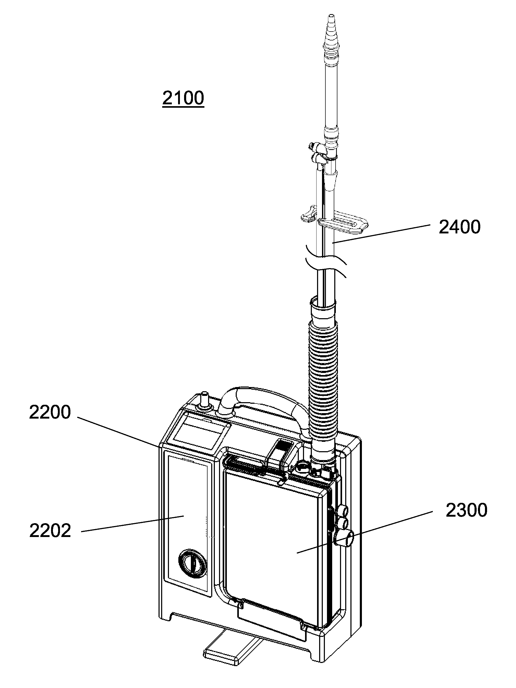
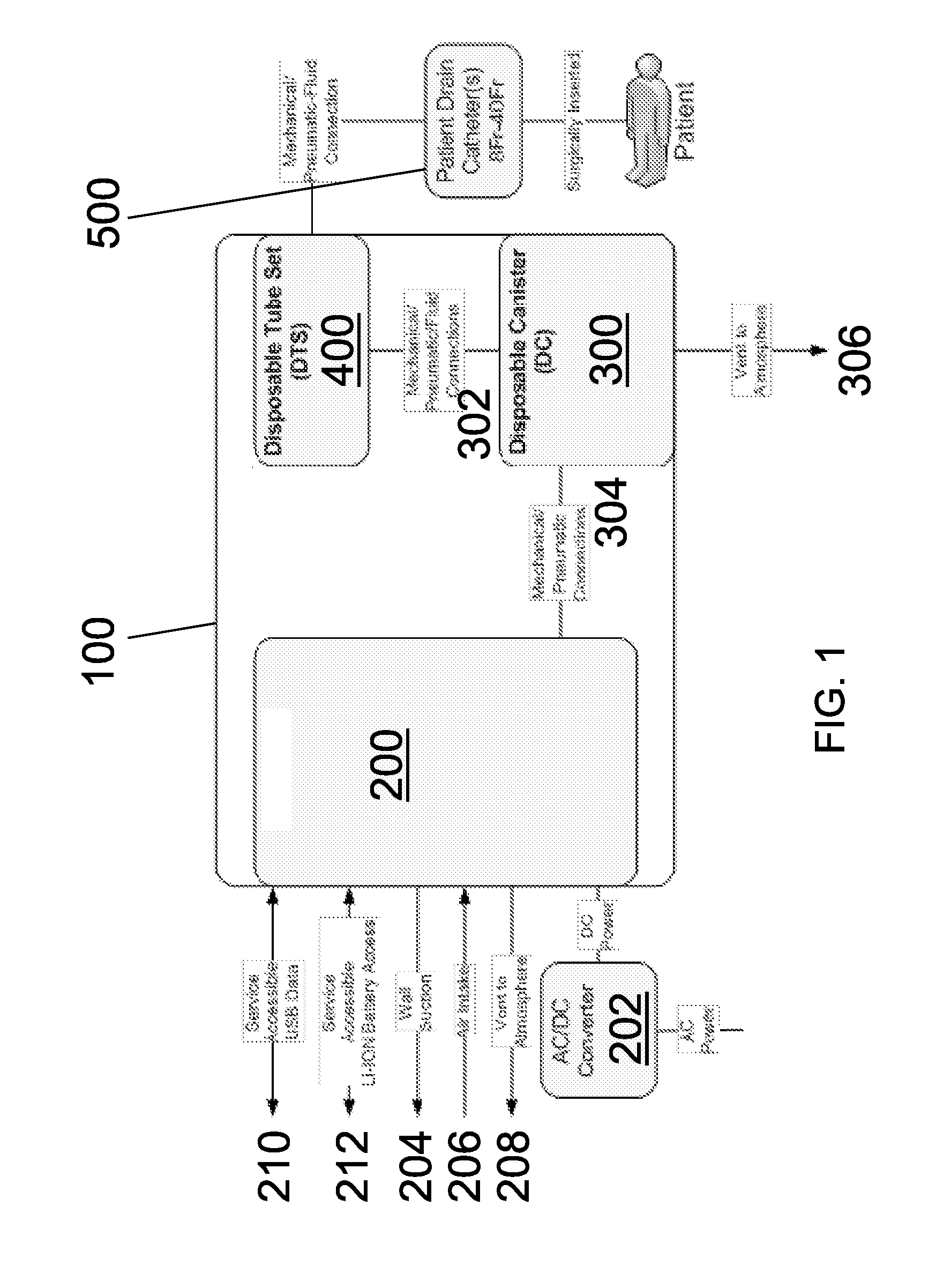
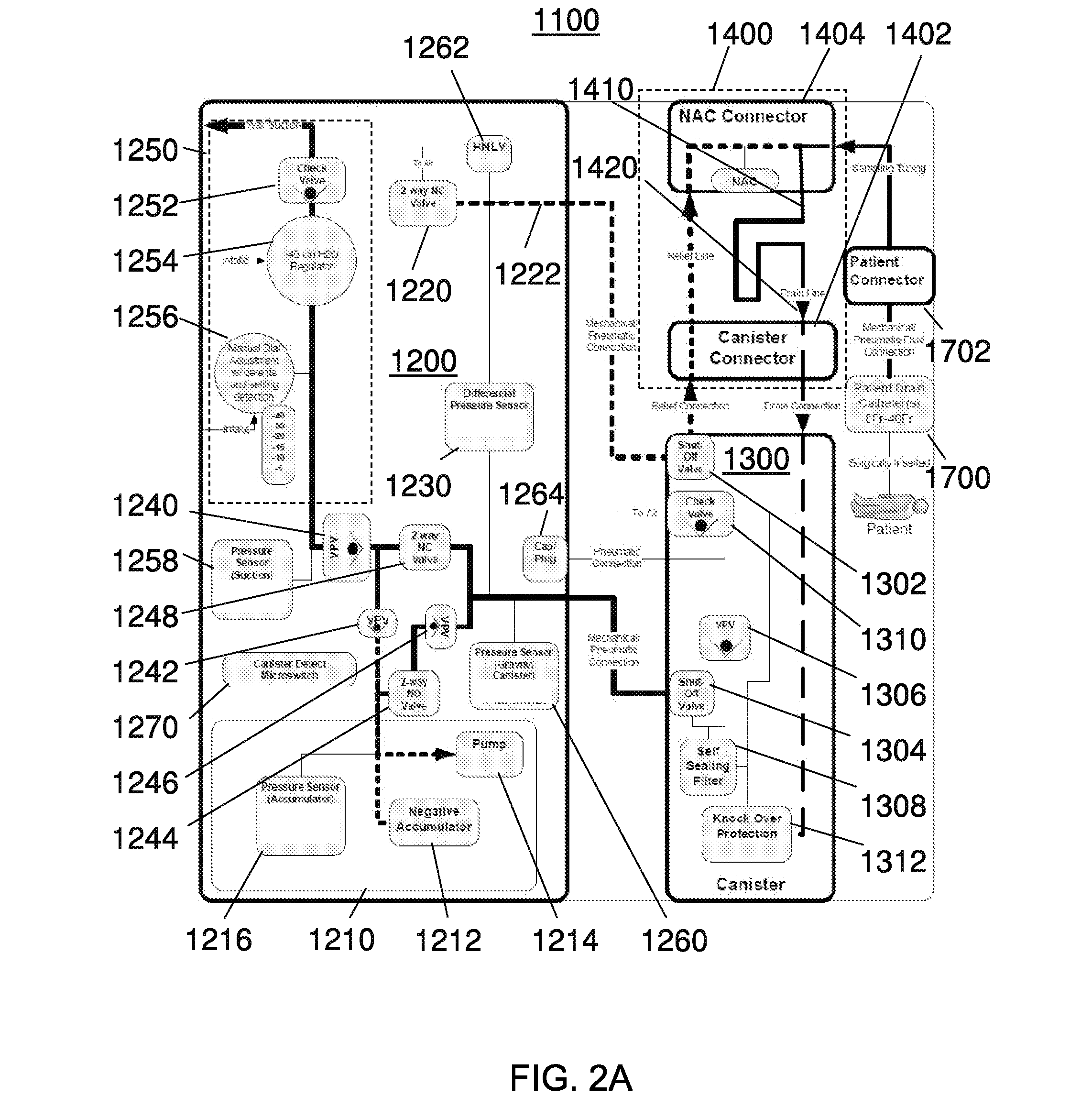
[0089]This invention will now be described with reference to several embodiments selected for illustration in the drawings. It will be appreciated that the scope and spirit of the invention are not limited to the illustrated embodiments. It will further be appreciated that the drawings are not rendered to any particular proportion or scale. Also, any dimensions referred to in the description of the illustrated embodiments are provided merely for the purpose of illustration. The invention is not limited to any particular dimensions, materials, or other details of the illustrated embodiments.

[0090]The exemplary systems and methods described herein are usable to drain or otherwise recover fluid from a patient. The systems and methods are described herein primarily with respect to draining the pleural cavity of a patient or to chest drainage for convenience according to embodiments of the invention selected for description and illustration. However, it will be understood by one of ordin...


PUM


Abstract

A chest drainage system includes a collection device and a fluid pathway configured to extend from the collection device to a patient. A pressure source is configured to selectively provide sub-atmospheric pressure to the fluid pathway. The system is configured to introduce sub-atmospheric pressure from the pressure source at a substantially constant target pressure and at a dynamic pressure that varies from the target pressure. A method is also disclosed for draining a pleural cavity of a patient. The method involves applying dynamic pressure to the pleural cavity of a patient by changing sub-atmospheric pressure applied to the patient such that the patient's pleura moves without any or limited patient activity, thus facilitating removal of loculated fluid from the pleural cavity. The method may involve the use of the chest drain system.

Description

CROSS REFERENCE TO RELATED APPLICATIONS[0001]This application claims the benefit of priority to U.S. Provisional Patent Application No. 61 / 856,427, filed Jul. 19, 2013, the content of which is incorporated herein by reference in its entirety.FIELD OF THE INVENTION[0002]The field of the invention relates generally to medical drainage systems, and more particularly to chest drainage systems.BACKGROUND OF THE INVENTION[0003]A number of fluid recovery systems have been developed for draining fluid, such as air and / or blood, from a patient. An example of such a fluid recovery system is a chest drainage system. Chest drainage systems are intended to remove fluid from the pleural space or the mediastinal cavity and to restore the sub-atmospheric pressure that is normally present in the pleural space. The systems are usually adapted to allow suction to be applied to the chest cavity to facilitate, among other things, the removal of fluid from the pleural space. Once the fluid has been remov...

Claims


Application Information

Patent Timeline
Patent Type & Authority Applications(United States)
IPC IPC(8): A61M1/00
CPCA61M1/0031A61M1/0033A61M2205/15A61M2205/52A61M2210/101A61M2205/3331A61M2205/50A61M2209/082A61M1/73A61M1/75A61M1/74A61M1/742
Inventor PEATFIELD, GREGORY
Owner ATRIUM MEDICAL
Why Eureka
Try Eureka