
Auto reset zip line

a technology of auto-reset and zip line, which is applied in transportation and packaging, rope railways, transportation and transportation, etc., can solve the problems of rider injury, further slowing down the ride, and difficult and time-consuming road transportation

Inactive Publication Date: 2016-07-07
DOSE CURTIS +1
View PDF4 Cites 5 Cited by
  • Summary
  • Abstract
  • Description
  • Claims
  • Application Information

AI Technical Summary

Benefits of technology

The invention is a safe and convenient auto reset zip line assembly. It consists of a cable running along the circumference of two pulleys that are fixedly coupled to a rigid frame. The pulleys have a continuous trough to retain the cable and are rotatably mounted on a shaft. The assembly also includes a braking mechanism and guarding plates to prevent derailing and entangling of the cable. The purpose of this invention is to provide a moving zip line that allows operators to easily rescue a rider who has stalled short of a lower station.

Problems solved by technology

Commonly known as a zip line, the system is extensively used in rough terrain and hilly areas where the road transport is difficult and time consuming.
Such a design of trolley moving downhill towards the end of a zip line has a disadvantage that on completion of each ride, the trolley system must be pulled back up to the upper starting point, or detached and carried back up to the starting point then reattached to the cable.
In addition, since the trolley slides along the stationary cable, there is significant danger that while sliding, the fingers, hair, or clothing of the rider can become tangled in the trolley wheels or the stationary cable, causing injury to the rider.
Ride operators have to ride backwards up the wire, hand over hand, to grab the rider's trolley and pull him or her into the lower station-a scary situation that further slows down the ride.

Method used


Image

  • Auto reset zip line
  • Auto reset zip line
  • Auto reset zip line

Examples


Embodiment Construction

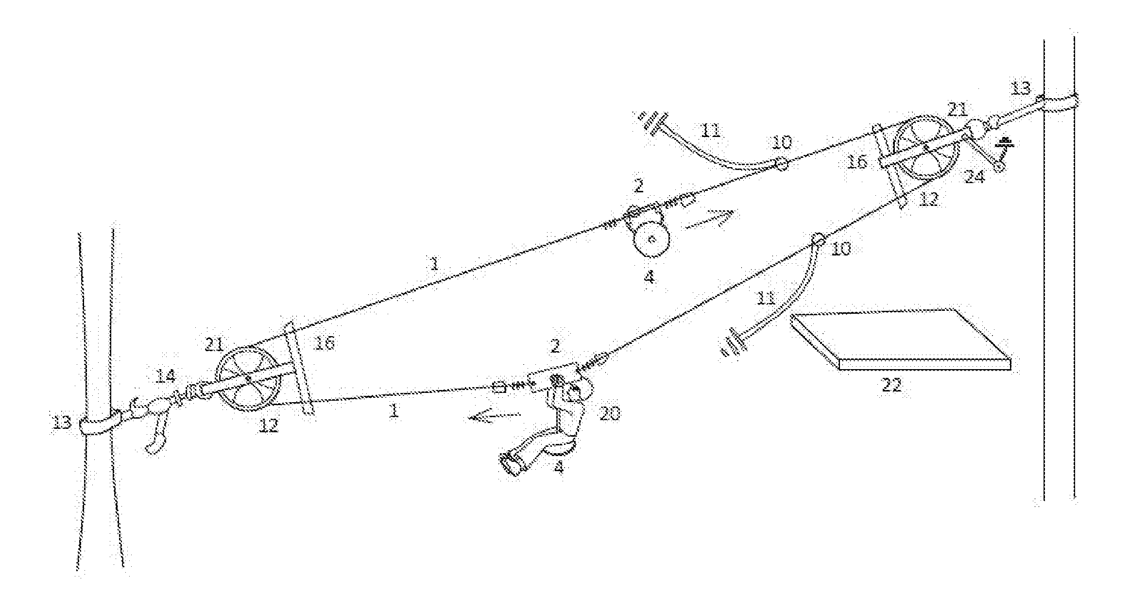
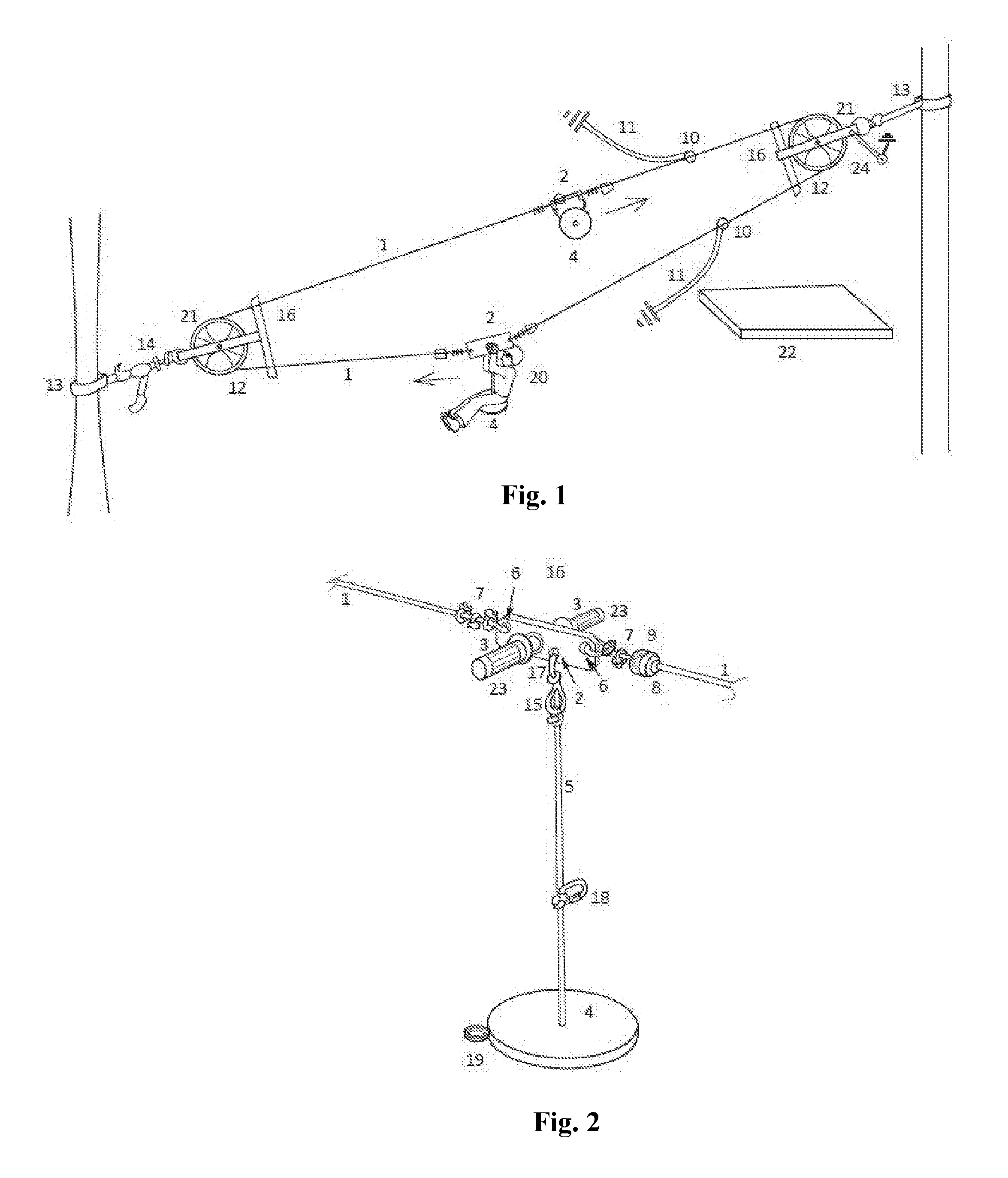
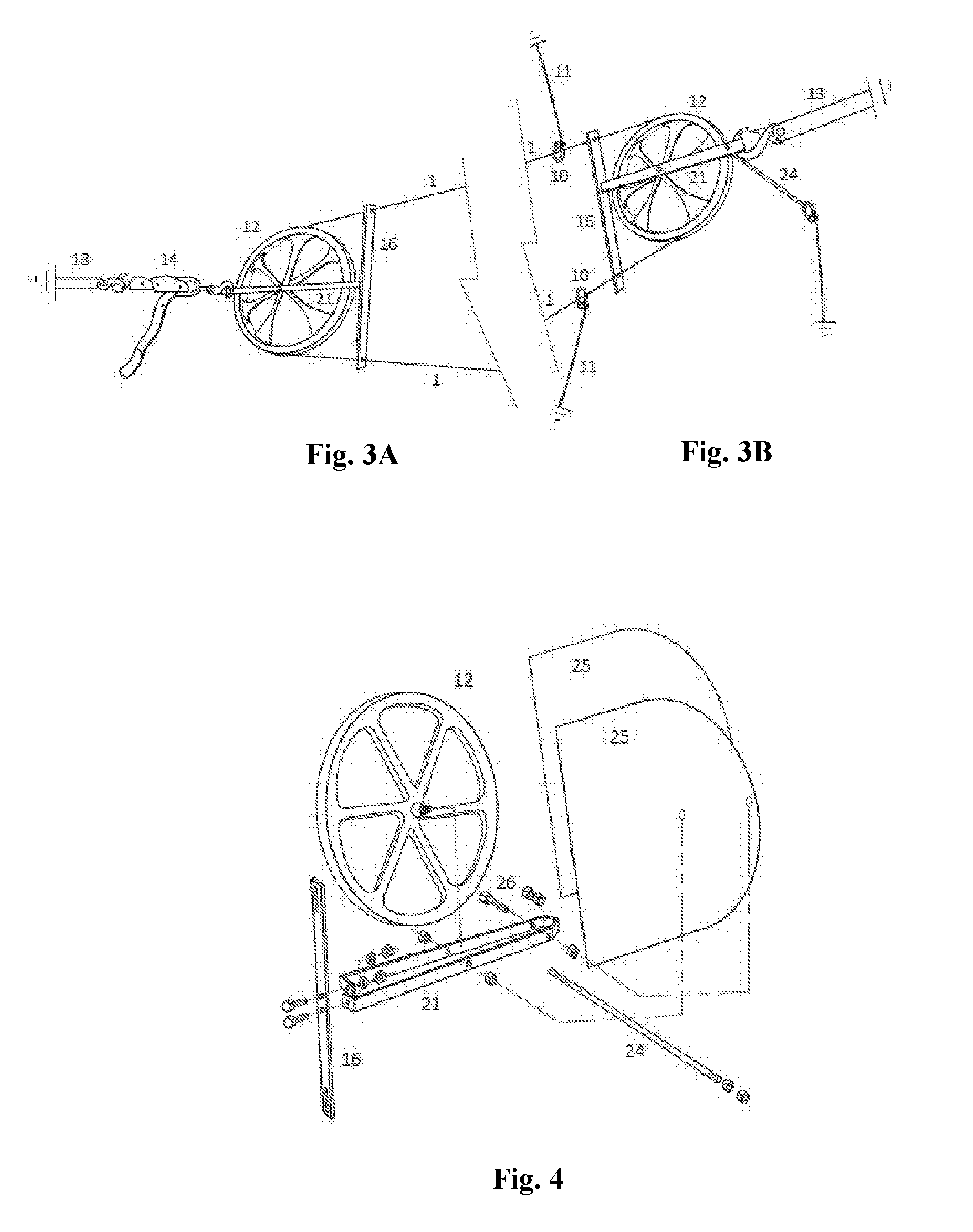
[0014]The present invention provides a zip line assembly for use in transporting a person downhill under gravity. Referring to FIG. 1, showing a child riding down the zip line, the zip line includes two equal-length 3 / 16 in. galvanized steel cables 1. The opposite ends of cable are coupled to a pair of rigid frame 2 and similarly the other cable is coupled to the same rigid frames, thus forming a continuous loop. The rigid frame more clearly shown in FIG. 2 includes a pair of handles 3 on opposite sides of the rigid frame. The handle could be a metal tube that is welded to the rigid frame and the metal tube could further include rubber or leather gripping adapted to be grabbed by a person riding on zip line. Further, as shown in FIGS. 1 & 2 is a seat 4 suspended from the rigid frame through a rope 5. Such an arrangement allows a person sitting on the seat and grabbing the handles with both hands to ride down the zip line. The rigid frames include two holes on opposite sides that per...


PUM


Abstract

An auto reset zip line assembly comprising a cable running along the circumference of two pulleys that are spaced apart forming a closed loop is disclosed. A pair of rigid frames are fixedly coupled to the cable at an equal distance from each other. The pulley includes a wheel having a rim that has a continuous trough along the circumference to retain the cable. The wheel is rotatably mounted on a shaft and the shaft is mounted to a hosing. The pulleys include means to suspend a zip line assembly between two vertical supports. The auto reset zip line assembly further comprises a braking mechanism and a pair of guarding plates coupled to the housing to prevent derailing and entangling of the cable. The invention is advantageous by providing a safe zip line assembly that obviated the need of returning a trolley to the starting point of the zip line.

Description

CROSS REFERENCE TO RELATED APPLICATION[0001]This patent application claims the benefit of U.S. Provisional Patent Application No. 62 / 099,803, filed Jan. 5, 2015, entitled “Auto Reset Zip Line” the entire teachings and the disclosure of which are incorporated herein by reference thereto.FIELD OF INVENTION[0002]The present invention is directed to a recreational suspended line transport system commonly known as zip lines and in particular to a downhill zip line system.BACKGROUND OF INVENTION[0003]Suspended cables between two vertical supports spaced apart have been commonly used to transport objects and persons from one place to another. Commonly known as a zip line, the system is extensively used in rough terrain and hilly areas where the road transport is difficult and time consuming. Having a person ride down these zip line systems has emerged as a popular and adventurous recreation sport. The zip line could be easily deployed in a backyard, parks or hilly terrains etc. Typically, ...

Claims


Application Information

Patent Timeline
Patent Type & Authority Applications(United States)
IPC IPC(8): A63G21/22A63G21/20B61B7/06B61H9/02
CPCA63G21/22B61B7/06A63G21/20B61H9/02B61B7/00F16D63/008
Inventor DOSE, CURTISTIERNEY, JOHN PAUL
Owner DOSE CURTIS
Learn More