Swirler

a swirler and air technology, applied in the field of swirlers, can solve the problems of difficult to manufacture swirlers radial flow, difficult to control the flow of fluid, and the performance of mixing air and fuel may degrade, and achieve the effects of less pressure drop, easy manufacturing and maintenance, and excellent mixing performan

Active Publication Date: 2016-07-07
HANWHA AEROSPACE CO LTD
View PDF1 Cites 10 Cited by
  • Summary
  • Abstract
  • Description
  • Claims
  • Application Information

AI Technical Summary

Benefits of technology

[0010]According to an aspect of the inventive concept, a swirler has excellent performance in mixing air with a fuel and stabilizing a flame, less pressure drop, and is easy to be manufactured and maintained.

Problems solved by technology

However, because only a direction of introduction fulid is changed without changing a velocity of the introduction fluid, the performance of mixing the air and the fuel may degrade.
As described above, the radial flow swirler is excellent in view of mixing the air and the fuel due to the rapid change in the velocity of the introduced air, but it is difficult to manufacture the radial flow swirler and to control the flow of fluid, compared to the axial flow swirler.

Method used


Image

  • Swirler
  • Swirler
  • Swirler

Examples


Embodiment Construction

Technical Problem

[0008]The inventive concept provides a swirler having excellent performance in mixing air and a fuel and stabilizing a flame, having less pressure drop, and is easy to be manufactured and maintained.

Technical Solution

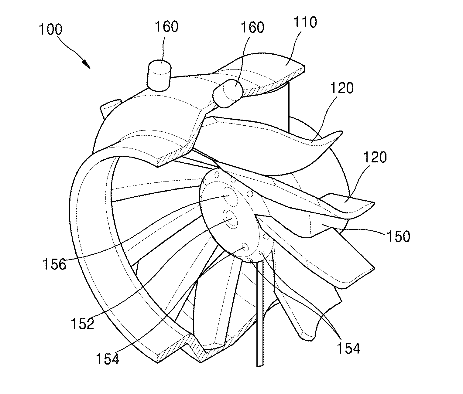
[0009]According to an aspect of the inventive concept, there is provided a swirler including a casing, a pilot body disposed in the casing, and a plurality of vanes arranged along a circumference of the pilot body, wherein at least a part of the vane protrudes further to a downstream than an end portion of the pilot body.

Advantageous Effects

[0010]According to an aspect of the inventive concept, a swirler has excellent performance in mixing air with a fuel and stabilizing a flame, less pressure drop, and is easy to be manufactured and maintained.

DESCRIPTION OF THE DRAWINGS

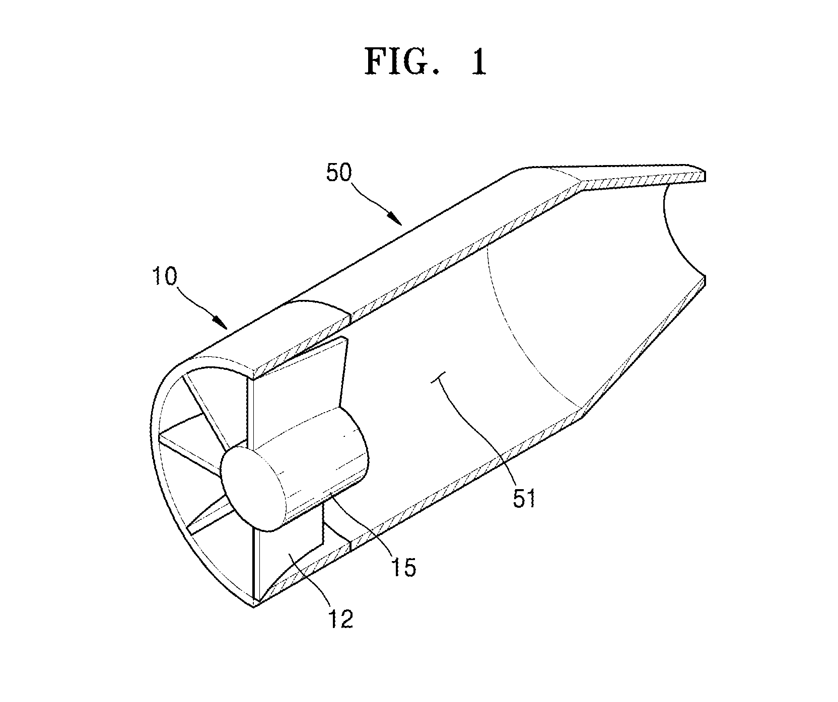
[0011]FIG. 1 is a partially cut perspective view of an axial flow swirler according to prior art;

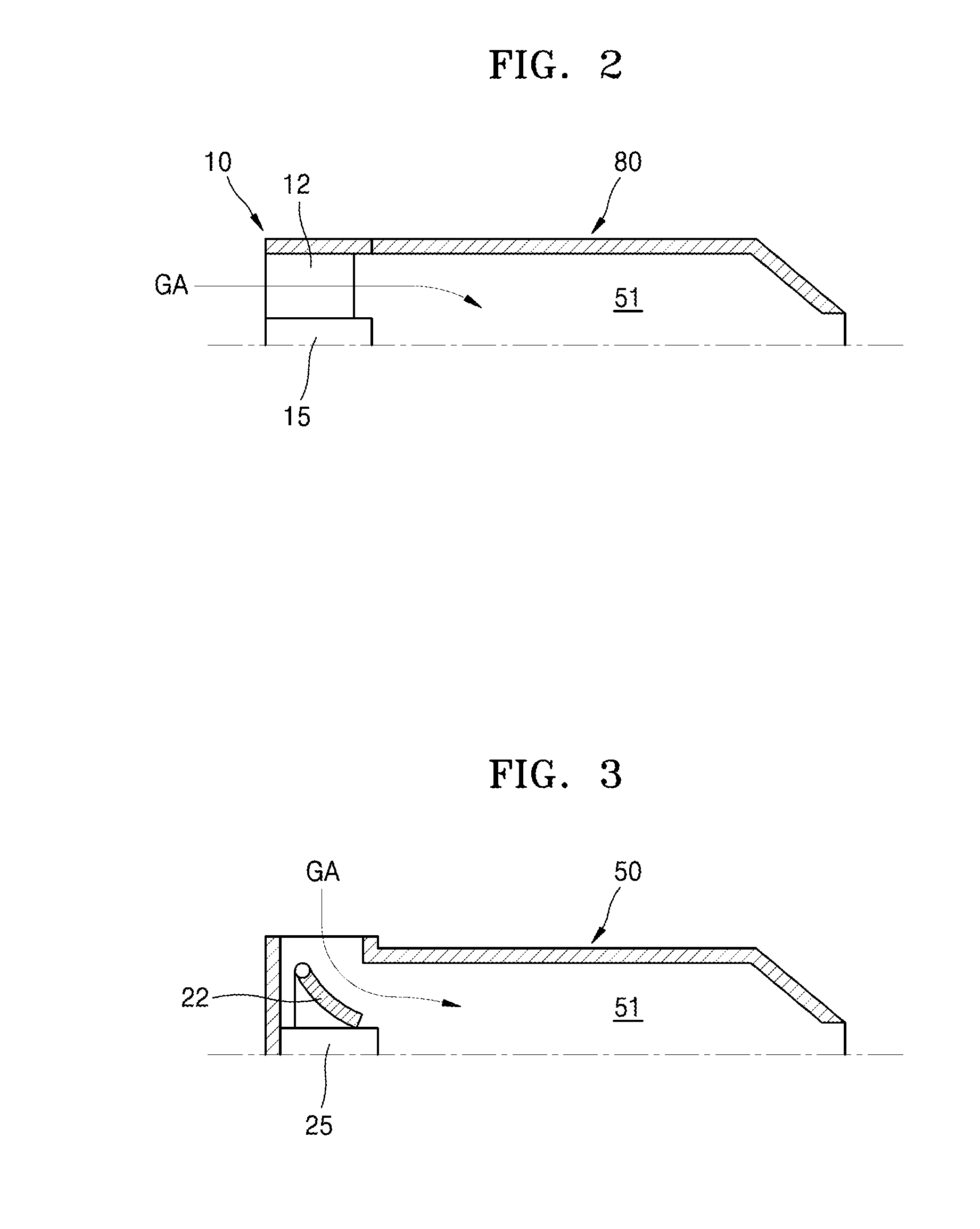
[0012]FIG. 2 is a schematic cross-sectional view showing a side of the axial flow swirle...


PUM


Abstract

The inventive concept relates to a swirler. According to an aspect of the inventive concept, there is provided a swirler including a casing, a pilot body disposed in the casing, and a plurality of vanes arranged along a circumference of the pilot body, wherein at least a part of the vane protrudes further to a downstream than an end portion of the pilot body.

Description

TECHNICAL FIELD[0001]The inventive concept relates to a swirler.BACKGROUND ART[0002]A swirler is used as a flame stabilizer of a pressure atomizing-type oil burner or a high pressure gas current atomizing-type oil burner, and swirls the air introduced into a burner by using swirl vanes. A mixture gas of the air introduced into the burner by the swirler and a fuel generates negative pressure in a center portion, and accordingly, generates a high temperature low-speed circulation region that may be ignited.[0003]Swirlers may be classified as axial flow swirlers and radial flow swirlers.[0004]FIG. 1 is a partially cut perspective view schematically showing an axial flow swirler, as an example of an axial flow swirler. In addition, FIG. 2 is a cross-sectional view of the axial flow swirler of FIG. 1, wherein a side of the axial flow swirler based on a symmetric axis is shown. Referring to FIGS. 1 and 2, an axial flow swirler 10 includes a plurality of vanes 12 that are disposed on an up...

Claims


Application Information

Patent Timeline
Patent Type & Authority Applications(United States)
IPC IPC(8): F23D11/38F23D11/44
CPCF23D11/44F23D11/383F23C7/004F23D11/40F23D14/24F23R3/14F23D11/24F23D14/62B05B7/04B05B7/0458B05B7/10F23D3/14F23D7/00F23D11/004F23D14/04
Inventor KIM, IK SOO
Owner HANWHA AEROSPACE CO LTD
Why Eureka
Try Eureka