Image processing apparatus and method for controlling the same

a technology of image processing and apparatus, applied in the field of image processing apparatus, can solve the problems of complex processing and periodical density non-uniformity in the output image, and achieve the effect of restrainting density non-uniformity due to distortion

Active Publication Date: 2016-07-07
CANON KK
View PDF2 Cites 7 Cited by
  • Summary
  • Abstract
  • Description
  • Claims
  • Application Information

AI Technical Summary

Benefits of technology

[0008]The present disclosure is directed to a technique capable of easily restraining the influence of spot areas distorted in shape and forming an image in which density nonuniformity due to the distortion is restrained.

Problems solved by technology

In the LED exposure type image forming apparatus, since reducing the lens size to about the pixel pitch is difficult, the arrangement interval of the lenses is larger than that of the light emitting elements.
Such spot areas distorted in shape in different directions cause a problem that periodical density nonuniformity occurs in an output image.
However, in the technique for correcting the energy of the light emitted from each light emitting element discussed in Japanese Patent Application Laid-Open No. 2009-179062, it is necessary to acquire an optimum correction amount for each light emitting element, resulting in complicated processing.

Method used


Image

  • Image processing apparatus and method for controlling the same
  • Image processing apparatus and method for controlling the same
  • Image processing apparatus and method for controlling the same

Examples


third exemplary embodiment

Effects of Third Exemplary Embodiment

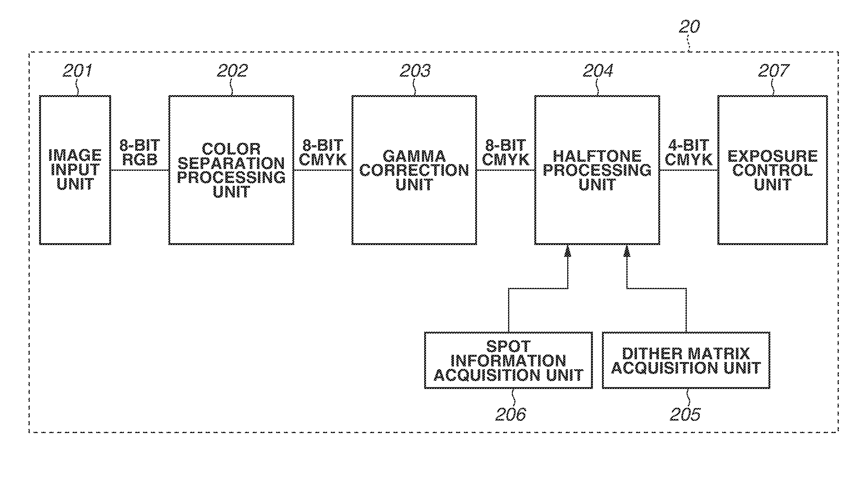
[0161]As described above, in the present exemplary embodiment, the image processing apparatus 20 stores three or more dither matrices corresponding to different halftone dot patterns. Further, based on the pixel position x, which is the position information of the target pixel, the image processing apparatus 20 derives the pixel phase P(x), which is phase information indicating the X-axis directional relative position of the LED element corresponding to the target pixel, with respect to the lenses that allow passage mainly of the light emitted from the relevant LED element. Then, the image processing apparatus 20 selects as a dither matrix to be used for halftone processing either one of three or more dither matrices corresponding to the pixel phase P(x).

[0162]In this case, the image processing apparatus 20 selects a dither matrix corresponding to a halftone dot pattern having more lighting contour pixels obliquely adjacent in a predetermined dir...


PUM


Abstract

An image forming apparatus includes a light emitting element group including a plurality of light emitting elements disposed at first intervals in a first direction, and configured to emit optical beams based on image data, a lens array including a plurality of lenses disposed at second intervals different from the first intervals in the first direction and configured to focus or condense the light emitted from the light emitting element group, and a halftone processing unit configured to perform halftone processing by using a dither matrix corresponding to a relative positional relationship between the plurality of light emitting elements and the plurality of lenses to generate the image data.

Description

BACKGROUND OF THE INVENTION[0001]1. Field of the Invention[0002]The present disclosure relates to an image processing apparatus for forming an image based on the electrophotographic process, and a method for controlling the image processing apparatus.[0003]2. Description of the Related Art[0004]In an electrophotographic image forming apparatus such as a laser beam printer and a copying machine, an exposure unit emits optical beams according to an exposure signal, forms an electrostatic latent image on the surface of a photosensitive member, and develops the electrostatic latent image through toner adhesion thereto. As an exposure method employed in the exposure unit of this electrophotographic image forming apparatus, the light emitting diode (LED) exposure method and the laser exposure method are known. In an LED exposure type image forming apparatus, light emitted from LED elements serving as light emitting elements is condensed on a photosensitive drum by lenses, respectively. A ...

Claims


Application Information

Patent Timeline
Patent Type & Authority Applications(United States)
IPC IPC(8): G06K15/02G06K15/14
CPCG06K15/1881G06K15/1876G06K15/14B41J2/475G06K15/1247G06K15/1868H04N1/191
Inventor OTANI, RYOSUKETAKIKAWA, YOICHI
Owner CANON KK
Why Eureka
Try Eureka