Baler and method of baling

a baler and baling technology, applied in the field of baler and baling method, can solve the problems of increasing un uniform expansion amount, and upper limit of compression pressure that can be applied to the baler, so as to reduce the risk of twine breaking

Active Publication Date: 2016-07-14
KUHN GELDROP
View PDF15 Cites 0 Cited by
  • Summary
  • Abstract
  • Description
  • Claims
  • Application Information

AI Technical Summary

Benefits of technology

[0020]It is an object of the invention to provide a baler and a method of baling that mitigate the problems identified above and, in particular, that allow optim

Problems solved by technology

However, this increased compacting pressure also increases the risk of the twines breaking when the bale is ejected from the baling chamber.
This places an upper limit on the compression pressure that can be applied to the bale.
However, the amount of expansion is not uniform.
There is therefore a greater risk that the twines will break when baling such materials.
However, this reduces the density and mass of the bale, which is generally undesirable.
However, this also has a negative impact on the mass and density of the bale and it results in a lower level of compression for all materials, including less elastic materials for which a lower level of compression is not needed.
Recently, the compression level that c

Method used


Image

  • Baler and method of baling
  • Baler and method of baling
  • Baler and method of baling

Examples


Embodiment Construction

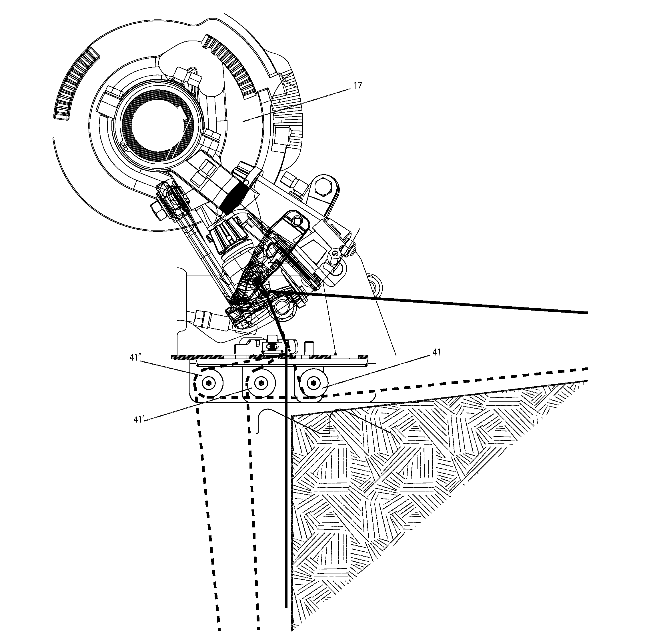
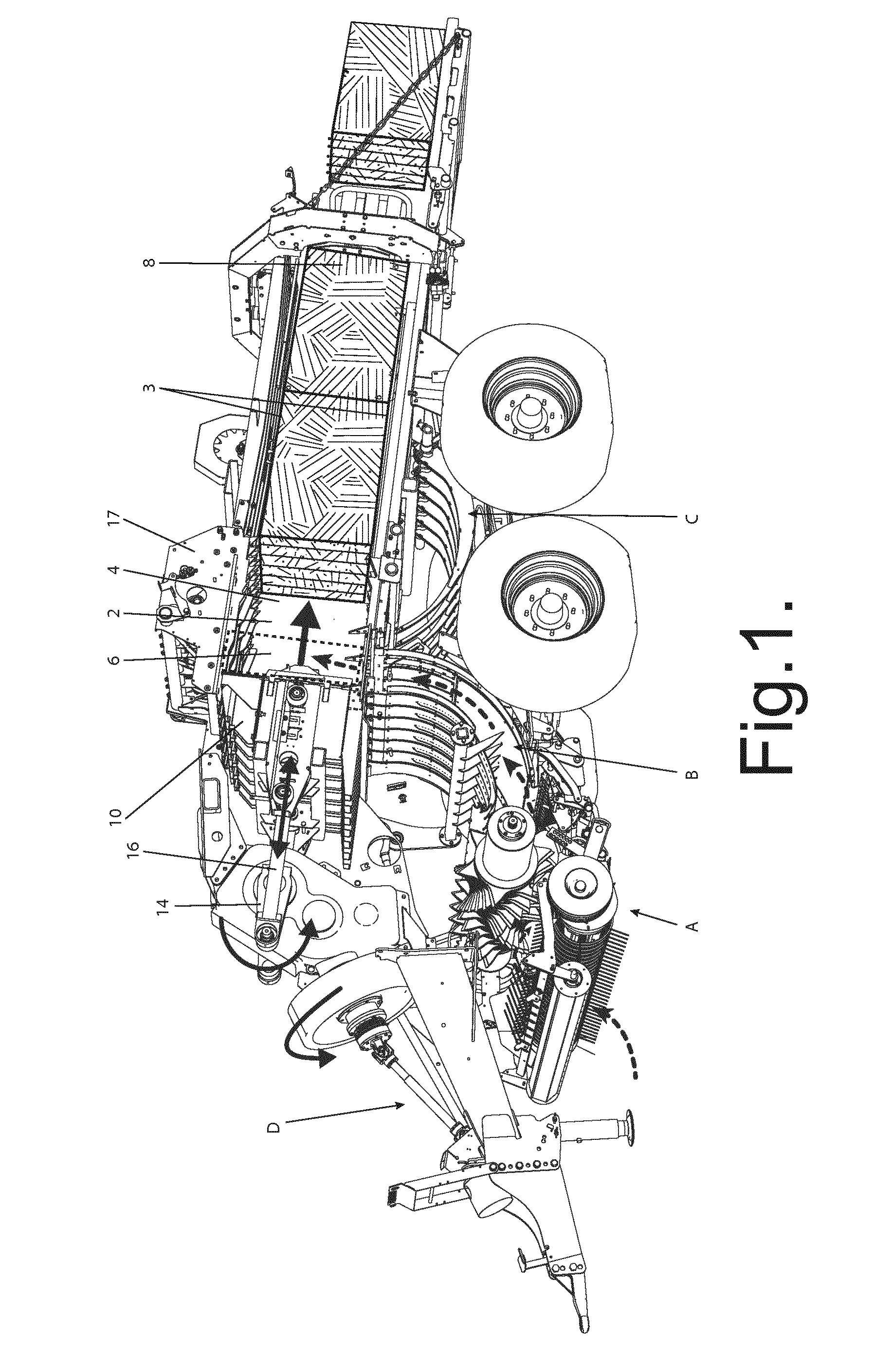
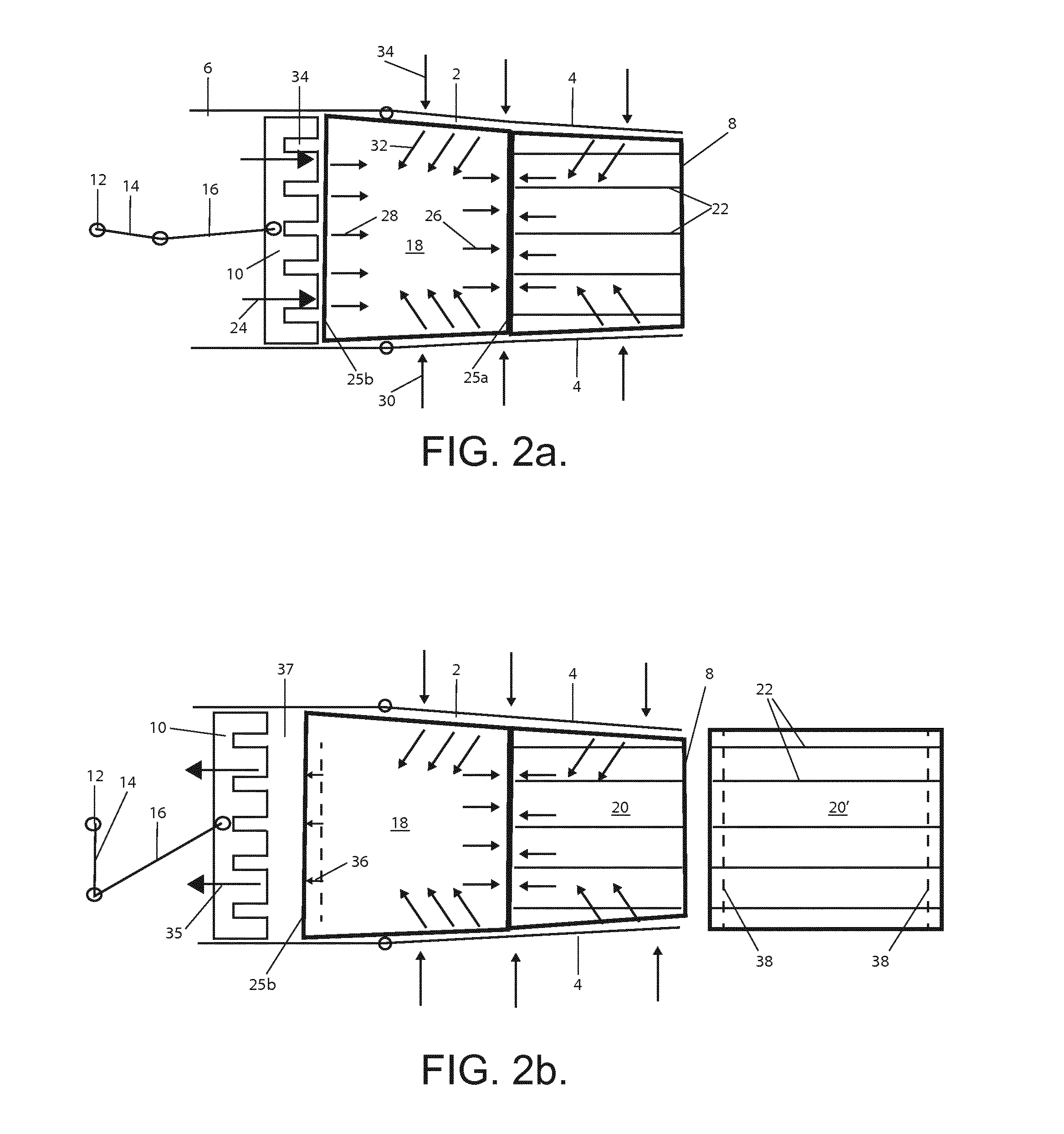
[0039]The baling machine or baler shown in FIG. 1 includes a baling chamber 2 that is defined by top and bottom plates 3 and two side walls 4, one of which has been omitted from the drawing to show the interior of the chamber 2. The baling chamber 2 comprises a channel having an inlet end6 and an outlet end 8. At the inlet end 6, the channel is closed by a plunger 10 that can be driven into the baling chamber 2 in a reciprocating manner. In this example, the plunger 10 is driven from a rotating drive axle 12 via a pair of drive arms 14, 16. The baling machine also includes a binding device 17, for example as described in U.S. Pat. No. 4,074,623, for binding the bale with binding twine.

[0040]In addition, the baling machine includes a pick up mechanism A for picking up cut bale material (for example grass and straw) from the ground, a feed mechanism B for feeding the bale material into the baling chamber 2, a set of needles C for feeding binding twine through the baling chamber and a ...


PUM


Abstract

A baler apparatus includes a baling chamber including at least one adjustable wall for adjusting compression of a body of bale material. A reciprocating plunger is operable to compress the bale material and a binding device binds the compressed material to form a bale by use of twine loops. An adjustment mechanism including a guide or rollers varies a length of the twine loops when binding the bale to reduce compression within part of the body of bale material and avoid twine breakage that can otherwise occur as a bale is ejected from the baler.

Description

[0001]The present invention relates to a baler and a method of baling, in particular but not exclusively for baling an agricultural crop.BACKGROUND TO THE INVENTION[0002]For efficient transport and storage, and to improve the keeping properties of the product, agricultural products like hay, straw and silage may be compressed into bales of a parallelepiped shape, which are known as ‘square’ bales. After the compression of the bale material the shape and the compression of the bale is maintained by binding the bale with twines that are looped around the compressed bale material. The ends of the twine are then knotted together.[0003]Typically, compression of the bale material is performed by a reciprocating plunger press baler. A typical baler of this type is described in U.S. Pat. Nos. 4,074,623 and 4,142,746 to Hesston Corporation. This baler machine includes a baling chamber comprising an open-ended channel through which bale material is forced by a reciprocating plunger. The plung...

Claims


Application Information

Patent Timeline
IPC IPC(8): A01F15/08A01F15/04A01F15/14
CPCA01F15/0825A01F15/042A01F15/145A01F15/14B65B63/02
Inventor AKKERMANS, DIONISIUS CORNELIS MARIA
Owner KUHN GELDROP
Why Eureka
Try Eureka