Retaining device having hooks

a technology of retaining device and hook, which is applied in the direction of snap fasteners, buckles, transportation and packaging, etc., can solve the problems of insufficient reliability of the wire fastening obtained by the use of abutment or clip fastening system, inability to undo the fastening without damaging the cover, and insufficient self-gripping fastening obtained between the cover fabric and the hooks situated in the bottom of the retaining elemen

Active Publication Date: 2016-07-14
APLIX INC
View PDF1 Cites 7 Cited by
  • Summary
  • Abstract
  • Description
  • Claims
  • Application Information

AI Technical Summary

Benefits of technology

[0008]One of the objects of the present invention is to provide a retaining device making it possible to remedy the above-mentioned drawbacks of the prior art, and in particular that makes it possible to provide fastening that is reliable, capable of withstanding traction, and that can be undone, should that be necessary, without damaging the cover.
[0014]With such an orientation, the hooks do not impede inserting the counterpart into the retaining groove, but they provide strong resistance to traction once they co-operate with the counterpart. When the counterpart is pulled away from the retaining groove in the main direction, the hooks work in shear and are very effective at preventing the counterpart from being extracted. With such a configuration, the force needed to disengage the counterpart has been measured as being at least twice the force that would be needed to obtain the same result if the hooks were arranged in the bottom of the retaining groove.
[0022]It can thus be understood that in use, a hook of the retaining element serves to retain a hook or a loop of the counterpart not only in the main direction, but also in the lateral direction of the retaining device because of the hooking portion of the hook, in particular by preventing the loop or the hook of the counterpart from disengaging by moving away from the side wall from which the hook extends. Typically, the retention cavity is wide enough to capture a hook or a loop of the counterpart, and deep enough to prevent the hook or the loop of the counterpart from becoming extracted from the retention cavity.
[0030]The retaining element, which is made by injection molding, is formed as a single piece, e.g. of thermoplastic material. It thus generally includes, on its outside surface, at least one zone of recessed or projecting shape that corresponds to the point where the molding material was injected. Fabrication of the retaining element by molding is easy and inexpensive.
[0036]The use of a magnetic material makes it possible, by co-operating with other magnetic elements, to hold the various elements of the retaining device in position while overmolding is taking place.
[0069]Such a molding device enables the hooks of the retaining element to be unmolded without stress or with limited stresses, and in particular without deforming them. The molding device also makes it possible to obtain hooks in a very wide variety of shapes (hooks having pointed ends, hooks having non-parallel faces, etc.).

Problems solved by technology

The fastening of the wire by means of abutment or clip-fastening as obtained with that system is not sufficiently reliable.
Furthermore, it is very difficult, if not impossible, to undo the fastening without damaging the cover.
During tests, it has been found that the self-gripping fastening obtained between the cover fabric and the hooks situated in the bottom of the retaining element is not entirely satisfactory, with the cover easily becoming detached from the retaining element when a traction force is applied thereto.

Method used


Image

  • Retaining device having hooks
  • Retaining device having hooks
  • Retaining device having hooks

Examples


first embodiment

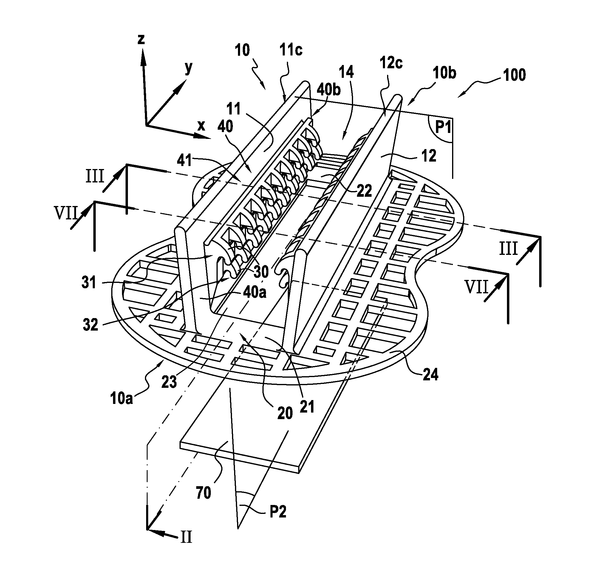
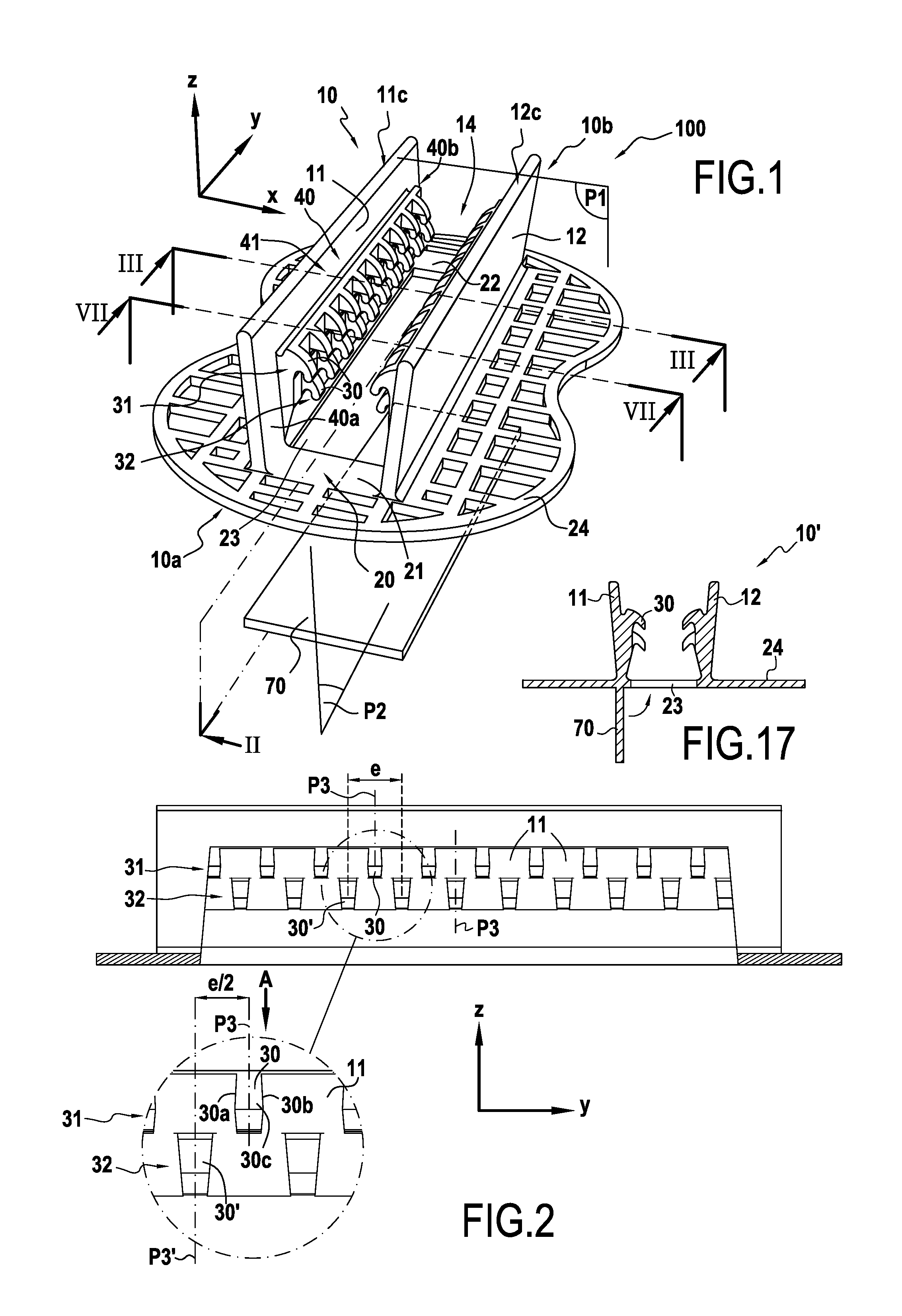
[0088]A retaining device 100 in a first embodiment is shown in particular in FIG. 1. Such a device is adapted to be placed in a mold used for making an article by molding, the molding material constituting the article possibly being a foam in particular, e.g. a thermoplastic or cured foam. The retaining device is thus overmolded by the article, once it has been molded. Advantageously, it then defines a bottom portion of a reception groove formed at the periphery of the article.

[0089]In the embodiment described below, the article having the retaining device 100 fastened thereto is a seat pad for a motor vehicle, which pad is made by molding.

[0090]Nevertheless, this example is not limiting. The article to which the retaining device 100 is fastened may be any other article, possibly not even molded, that needs to be associated with a cover. It is also possible to envisage fastening the retaining device of the invention in a manner other than by overmolding, e.g. by adhesive, welding, m...

fifth embodiment

[0128]In a fifth embodiment shown in FIG. 17, the bottom element 70 may also be made integrally with the retaining element 10′ while molding said element 10′. Under such circumstances, the bottom element 70 is a foldable portion, generally secured to the base 20 and adapted to be folded between an initial position in which it does not close the opening 23 in the base 20 and a position in which it covers the opening 23.

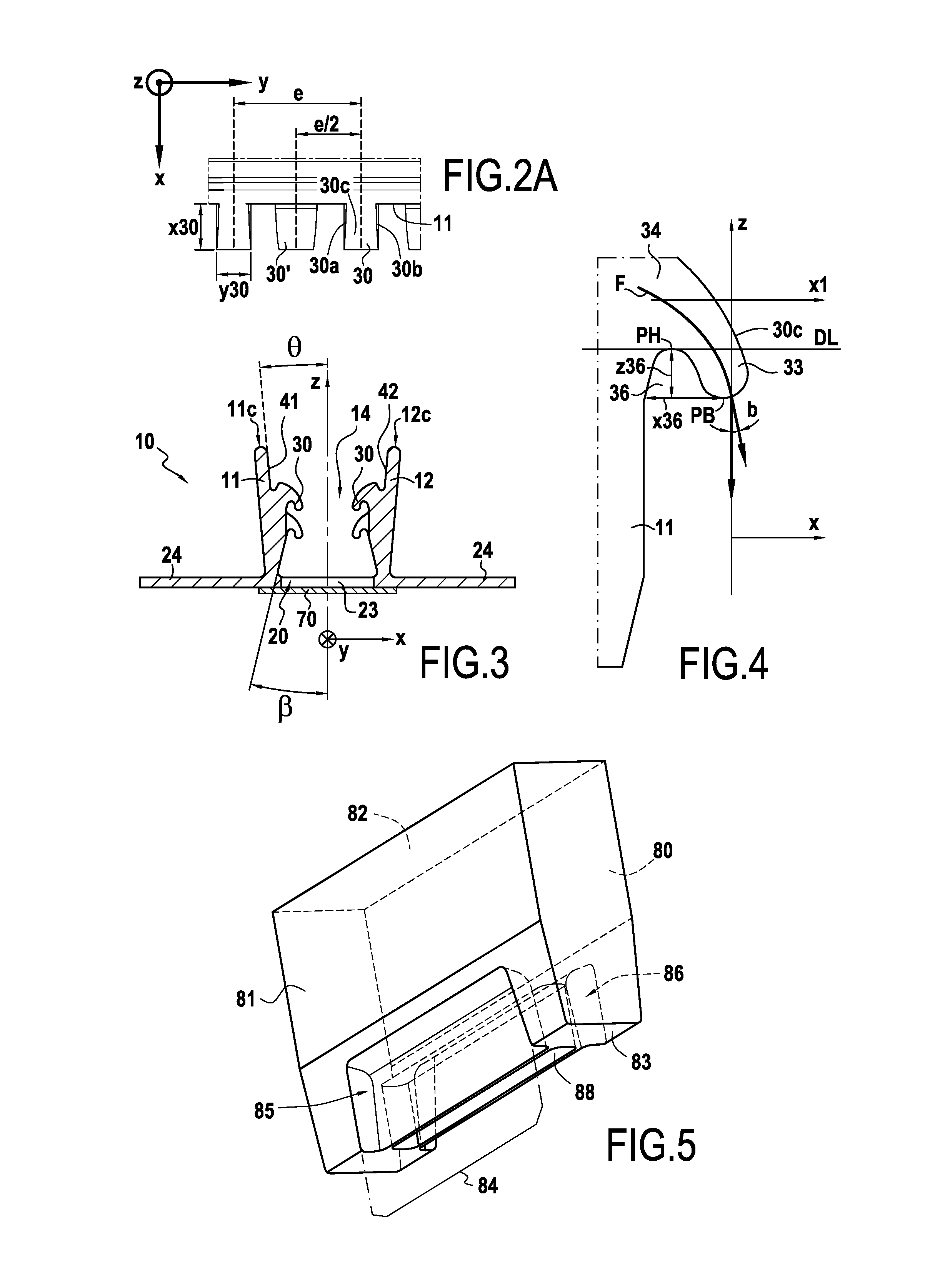
[0129]In order to protect the hooks while molding the vehicle seat pad, thereby preserving their gripping properties, the retaining device may also include a pedestal 80 of the type shown in FIG. 5.

[0130]The pedestal 80 is adapted to co-operate with the retaining element 10 and possibly with the bottom element 70 during molding of the pad 101. As shown in FIG. 5, the pedestal 80 presents the form of a low wall having its top 83 pointing towards the base 20 of the retaining element 10 when the retaining device 100 is in its mounted position.

[0131]In order to enable the ...


PUM

PropertyMeasurementUnit
widthaaaaaaaaaa
widthaaaaaaaaaa
depthaaaaaaaaaa

Abstract

A hooked retaining device (100) for defining at least a portion of a reception groove formed at the periphery of an article comprises a retaining element (10) made by injection molding. The retaining element has a first side wall (11) and a second side wall (12) that are spaced apart from each other in a lateral direction, and a base (20) connecting together said side walls (11, 12). The side walls (11, 12) and the base (20) define a retaining groove (14) that is open in a main direction (z) in order to receive a counterpart having hooks or loops. According to the invention, at least one of the side walls (11, 12) presents a plurality of hooks (30) adapted to co-operate with the counterpart, each hook (30) having at least one hooking portion oriented towards the base (20) of the retaining element (10).

Description

TECHNICAL FIELD[0001]The present description relates to a hooked retaining device, i.e. a device having hooks, that is suitable for being fastened to an article in order to fasten a cover on the article by means of the hooks of the retaining device co-operating with a counterpart having hooks or loops and that is secured to the cover.[0002]The retaining device of the present invention is particularly suitable for fastening a cover of the slipcover type on an article, in particular a molded article, such as a motor vehicle seat pad.BACKGROUND OF THE INVENTION[0003]A motor vehicle seat is constituted by a molded pad, generally made of foam, covered by a cover, e.g. made of fabric or of leather. At present, in order to fasten a cover fabric on the outside surface of a motor vehicle seat pad, one or more retaining elements are placed in one or more reception grooves formed at the periphery of the pad, which retaining elements are suitable for co-operating with the covering by clip-faste...

Claims


Application Information

Patent Timeline
Patent Type & Authority Applications(United States)
IPC IPC(8): A44B18/00A47C31/02B29C45/44
CPCA44B18/0049B29C45/44A44B18/0073A47C31/023A44B18/0061A44B18/0084A44B18/0076B29C44/1271B60N2/5825B60N2/5841B60N2/5833
Inventor MAHE, ANTHONYBOSSER, DAMIEN PIERRE ANTOINE
Owner APLIX INC
Why Eureka
Try Eureka