Drive Mechanism for a Needle Insertion Arrangement

a technology of a drive mechanism and a needle insertion arrangement, which is applied in the direction of medical syringes, intravenous devices, needles infusion, etc., can solve the problems of presenting a number of risks and challenges for users and healthcare professionals, and achieve the effect of improving the drive mechanism

Active Publication Date: 2016-07-14
SANOFI AVENTIS DEUT GMBH
View PDF9 Cites 24 Cited by
  • Summary
  • Abstract
  • Description
  • Claims
  • Application Information

AI Technical Summary

Benefits of technology

[0005]It is an object of the present invention to provide...

Problems solved by technology

Administering an injection is a process which presents a number of risks and challenges for users and healthcare professionals, both mental and physical.
During manual insertion o...

Method used


Image

  • Drive Mechanism for a Needle Insertion Arrangement
  • Drive Mechanism for a Needle Insertion Arrangement
  • Drive Mechanism for a Needle Insertion Arrangement

Examples


Embodiment Construction

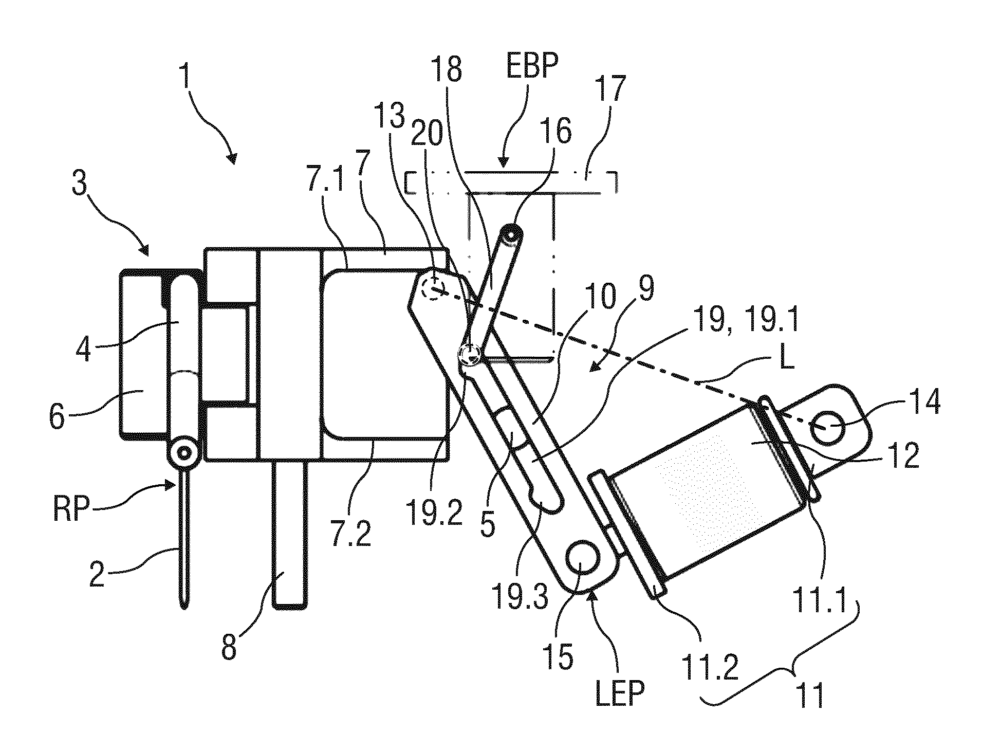
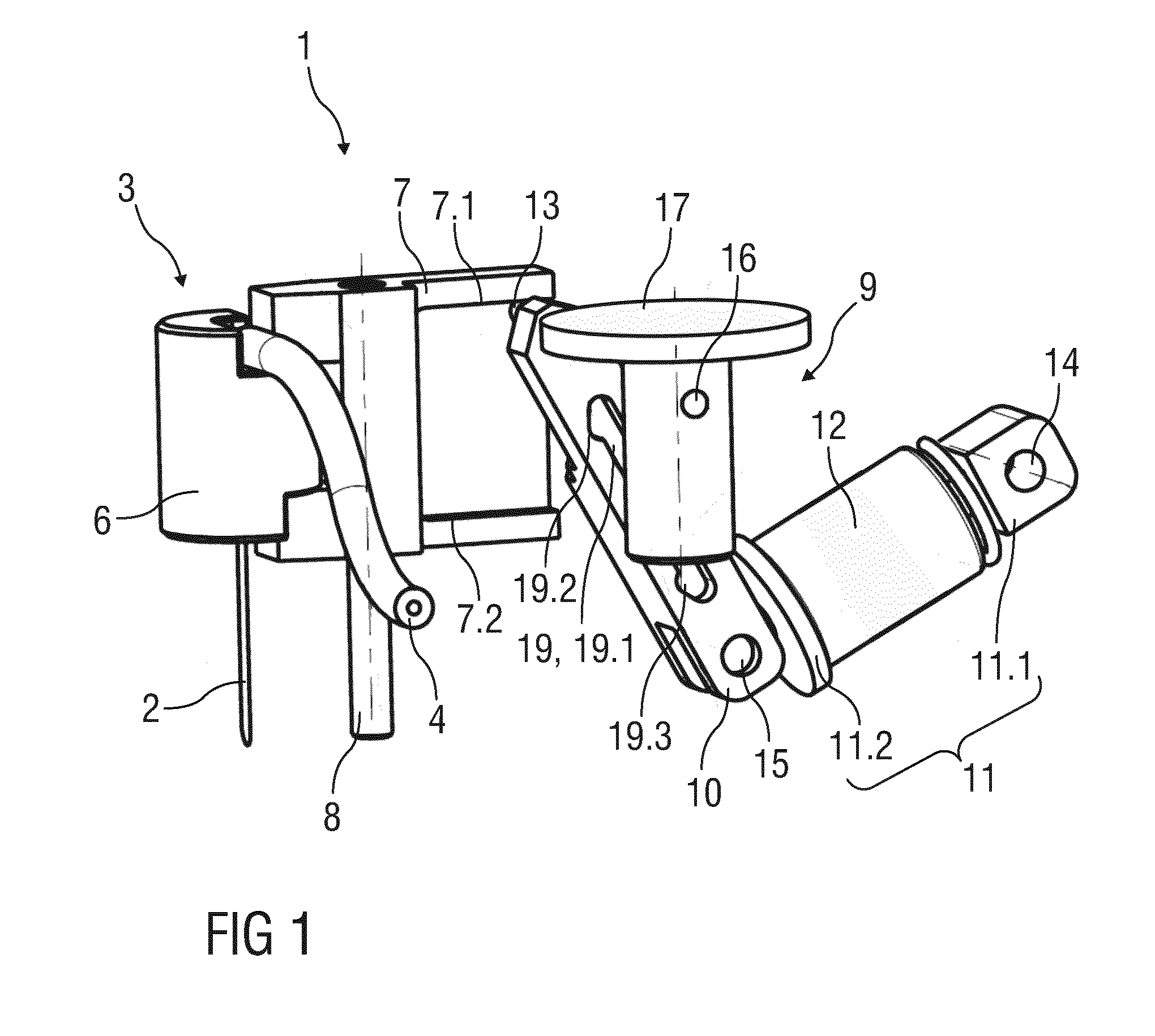
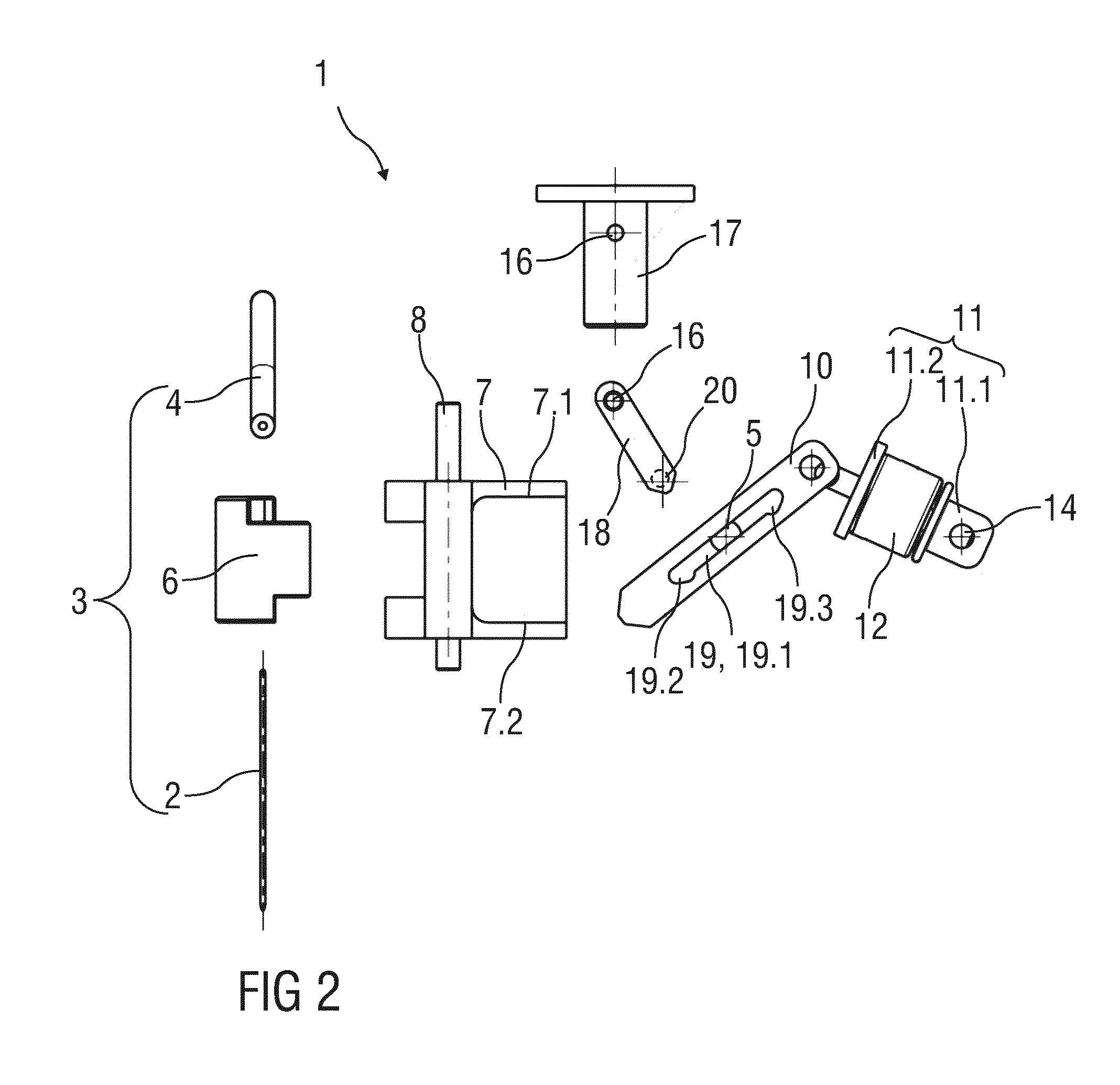
[0041]FIG. 1 is a schematic perspective view of an exemplary first embodiment of an insertion arrangement 1 for automatically or semi-automatically inserting an injection needle 2 into an injection site. FIG. 2 is a related exploded view. The injection may be performed manually or by a motor. The arrangement 1 may be applied in medicament pumps, e.g. insulin pumps which may be permanently worn on the body.

[0042]The injection needle 2 is part of a disposable unit 3, further comprising a tube 4 for establishing a fluid communication of the needle 2 with a drug container (not illustrated) and comprising a needle base 6, to which the injection needle 2 may be fixed for mechanically connecting the needle 2 to a drive mechanism 9 of an injection unit (not illustrated). The needle base 6 is inserted in a forked needle retainer 7 which is arranged to be moved up and down in a linear guide 8. This linear movement corresponds to insertion of the needle 2 into the injection site, e.g. subcutan...


PUM


Abstract

The invention relates to a drive mechanism (9) for a needle insertion arrangement (1), the drive mechanism (9) being arranged as a bistable mechanism with at least one pivoted link (10, 11) having two stable end positions (LEP, UEP) and an instable transitional central position (CP), the drive mechanism (9) further comprising a spring (12) biasing the link (10, 11) out of the transitional central position (CP), wherein at least one trigger unit (17, 21) is arranged for moving the link (10, 11) out of at least one of the stable end positions (LEP, UEP) towards and beyond the transitional central position (CP) against the bias of the spring (12).

Description

TECHNICAL FIELD[0001]The invention relates to a drive mechanism for a needle insertion arrangement.BACKGROUND OF THE INVENTION[0002]Administering an injection is a process which presents a number of risks and challenges for users and healthcare professionals, both mental and physical. During manual insertion of an injection needle into an injection site, e.g. the skin of a patient, it may be difficult to avoid tilting and bending of the needle and the insertion may be slow thus causing pain.[0003]There remains a need for an improved drive mechanism for a needle insertion arrangement.[0004]EP 1 764 037 A1 discloses a device for collecting body fluids, the device having a pricking unit prickable in a body part, and a drive that is provided for forward and backward running pricking movement of the pricking unit. The drive has actuator wires on the basis of a shape memory alloy (SMA) for control of the pricking movement by a change of wire length. The wires serve as brake unit for braki...

Claims


Application Information

Patent Timeline
IPC IPC(8): A61M5/32A61M5/34
CPCA61M5/34A61M5/3287A61M5/158A61M2005/1585
Inventor SCHABBACH, MICHAELWERNER, MEINOLFZECKAI, OLAFNZIKE, PHILIPPE
Owner SANOFI AVENTIS DEUT GMBH
Why Eureka
Try Eureka