Ventilation Appartus
a technology of ventilation apparatus and air intake, which is applied in the direction of ventilation systems, lighting and heating apparatus, heating types, etc., can solve the problems of gradual reduction of indoor air quality, and achieve the effect of improving the efficiency of heat exchange between the heat exchanger and air and minimizing the resistance of air
- Summary
- Abstract
- Description
- Claims
- Application Information
AI Technical Summary
Benefits of technology
Problems solved by technology
Method used
Image
Examples
first embodiment
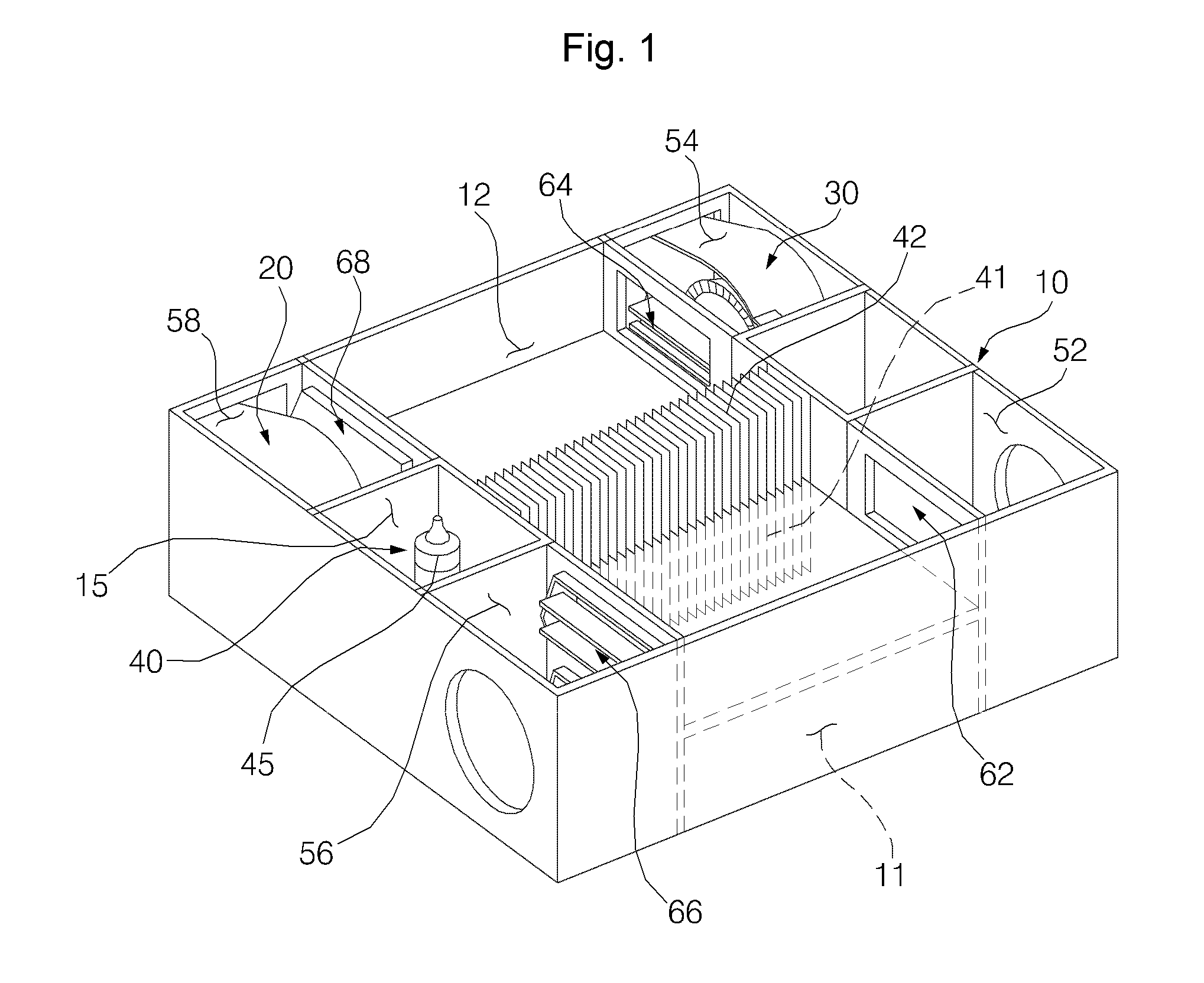
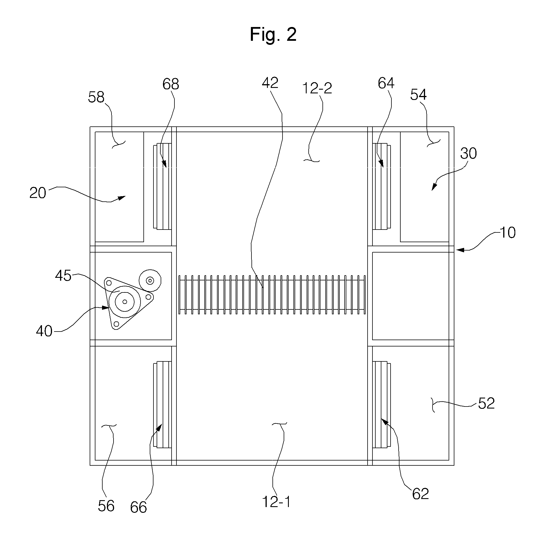
[0060]An operation of the ventilation apparatus in accordance with the present invention is described in detail below with reference to related drawings.
[0061]Ventilation Mode
[0062]In ventilation mode, some of an indoor air is discharged to the outside, and fresh air is sucked from the outside and supplied to the inside.
[0063]In this case, in the ventilation apparatus according to the present embodiment, while the ducts in the first floor and the second floor are alternately open and closed, an outdoor air is supplied to the inside, and an indoor air is discharged to the outside.
[0064]For example, a case where an outdoor air is supplied to the inside through the first floor and an indoor air is discharged to the outside through the second floor is described below (refer to FIG. 4).
[0065]First, in order to supply the outdoor air to the inside, the first outdoor suction damper 66-1 and the first indoor discharge damper 64-1 disposed in the first floor are open, and the remaining dampe...
second embodiment
[0095]FIG. 8 is an exemplary diagram illustrating that the duct structure of a ventilation apparatus in accordance with the present invention is divided into the first floor and the second floor in order to describe the duct structure.
[0096]The ventilation apparatus according to the present embodiment includes a plurality of heat exchangers disposed in a single layer, unlike in the first embodiment.
[0097]More specifically, the ventilation apparatus according to the present embodiment may include two first heat exchangers 41-1 and 41-2. One (e.g., 41-1) of the two first heat exchangers is installed close to the first indoor discharge damper 64-1, and the other (e.g., 41-2) of the two first heat exchangers is installed close to the first outdoor discharge damper 68-1.
[0098]Furthermore, one (e.g., 42-1) of two second heat exchangers is installed close to the second indoor discharge damper 64-2, and the other (e.g., 42-2) of the two second heat exchangers is installed close to the secon...
third embodiment
[0103]FIG. 9 is an exemplary diagram illustrating that the duct structure of a ventilation apparatus in accordance with the present invention is divided into the first floor and the second floor in order to describe the duct structure.
[0104]The ventilation apparatus according to the present embodiment may further include a guide configured to guide the flow of air and installed in at least one of the first sharing duct 11 and the second sharing duct 12.
[0105]In the present embodiment, the guide may include a first suction guide 71-1 and a first discharge guide 71-2 installed in the first sharing duct 11 and a second suction guide 72-1 and a second discharge guide 72-2 installed in the second sharing duct 12.
[0106]In this case, the first suction guide 71-1 is configured to guide sucked air to the first heat exchanger 41, and the second suction guide 72-1 is configured to guide sucked air to the second heat exchanger 42.
[0107]Furthermore, the first discharge guide 71-2 is configured t...
PUM
 Abstract
Description
Claims
Application Information
 - R&D
- Intellectual Property
- Life Sciences
- Materials
- Tech Scout
- Unparalleled Data Quality
- Higher Quality Content
- 60% Fewer Hallucinations
Browse by: Latest US Patents, China's latest patents, Technical Efficacy Thesaurus, Application Domain, Technology Topic, Popular Technical Reports.
© 2025 PatSnap. All rights reserved.Legal|Privacy policy|Modern Slavery Act Transparency Statement|Sitemap|About US| Contact US: help@patsnap.com


