Translationally movable wind power plant

a technology of wind power plant and wind turbine, which is applied in the direction of machines/engines, battery/cell propulsion, greenhouse gas reduction, etc., can solve the problems of a large amount of gathered energy, a high fuel consumption of road vehicles, and a sporadic flow of air in many areas, so as to reduce turbulence, improve the yield of produced electrical energy, and reduce the effect of pressur

Pending Publication Date: 2022-03-17
FRANCK JAN
View PDF19 Cites 0 Cited by
  • Summary
  • Abstract
  • Description
  • Claims
  • Application Information

AI Technical Summary

Benefits of technology

[0028]Thereby, the air resistance of the road vehicle is not increased by a greater size of the body of the vehicle or by extensions fixed to the body of the vehicle housing the wind generator. Furthermore, as there is no cascade of several wind wheels behind each other, neither in the direction of travel of the road vehicle nor in the direction of the airflow through the wind wheels, the obstacle of the wind wheel is minimized while the efficiency of the wind generator is maximized. A further measure to minimize the air resistance is to use a wind wheel with a shorter extension in the direction of its rotational axis compared to its extension in a transverse direction.
[0070]A wind wheel with a vertical axis of rotation converts flow energy of wind into rotational energy independent of the flow direction of the wind. Therefore, such embodiment can generate energy even if the vehicle is not moving, if a wind strength is sufficient.

Problems solved by technology

However, the wind flow in many areas is somewhat sporadic, and it is not uncommon for periods with high wind to be interspersed with calm or windless phases.
In addition, during periods with low wind, the massive rotor of a wind power plant often cannot be set in motion, so that wind energy plants generally are able to deliver energy only at higher wind speeds.
As seen from a reference system connected to the body of the travelling road vehicle, this air resistance results in a rather strong airstream bouncing against the front face of the road vehicle and flowing from the front side of the road vehicle to the rear side thereof.
Therefore, the gathered energy has to be paid dearly by a higher fuel consumption of the road vehicle.
A similar disadvantage has to be tolerated at another construction disclosed in U.S. Pat. No. 7,808,121 B1, where wind wheels are mounted within a housing which is fixed to the roof of the road vehicle.
On the other hand, such a housing rises far beyond the roof of the road vehicle and produces an additional air resistance in case of travel, and therefore, the fuel consumption of such road vehicle is substantially higher than without such roof extensions.
Another problem with US 2008 / 0296904 A1 as well as with U.S. Pat. No. 7,808,121 B1 is that in most embodiments disclosed in these documents, there are several wind generators installed behind each other in the direction of travel of the road vehicle.
Furthermore, as can be seen from the drawing of U.S. Pat. No. 7,665,554 B1, the common air conduit for the wind generators requires a great amount of space within the car and the length of the motor hood is more as double the diameter of a front wheel, although it does not house the motor of the vehicle at all.
This tremendous waste of space raises the weight of the road vehicle, and therefore results in an additional fuel consumption of the road vehicle.
A similar drawback occurs at the U.S. Pat. No. 5,680,032.
Altogether, such duct system not only consumes a high amount of space within the engine compartment, but extends beneath the chassis and underbody of the vehicle up to the tail end of the car, and therefore leads to a substantially higher weight of the vehicle, which in turn raises the fuel consumption of the vehicle.
Such an arrangement produces an obstacle thwarting the air stream in the duct system between the air intake duct and the air discharge rather completely.
The insofar blocked air stream raises the air resistance of the road vehicle and leads to a raised fuel consumption.
Although such an arrangement constitutes a rather significant obstacle for the airstream braking, the electrical output is limited.
Altogether, all known documents of the prior art disclose arrangements with a raised air resistance and / or weight of the vehicle, while the gathered electrical energy is poor and cannot redeem the raised fuel consumption of the vehicle resulting from the raised air resistance and / or weight of the vehicle.

Method used


Image

  • Translationally movable wind power plant
  • Translationally movable wind power plant
  • Translationally movable wind power plant

Examples


Embodiment Construction

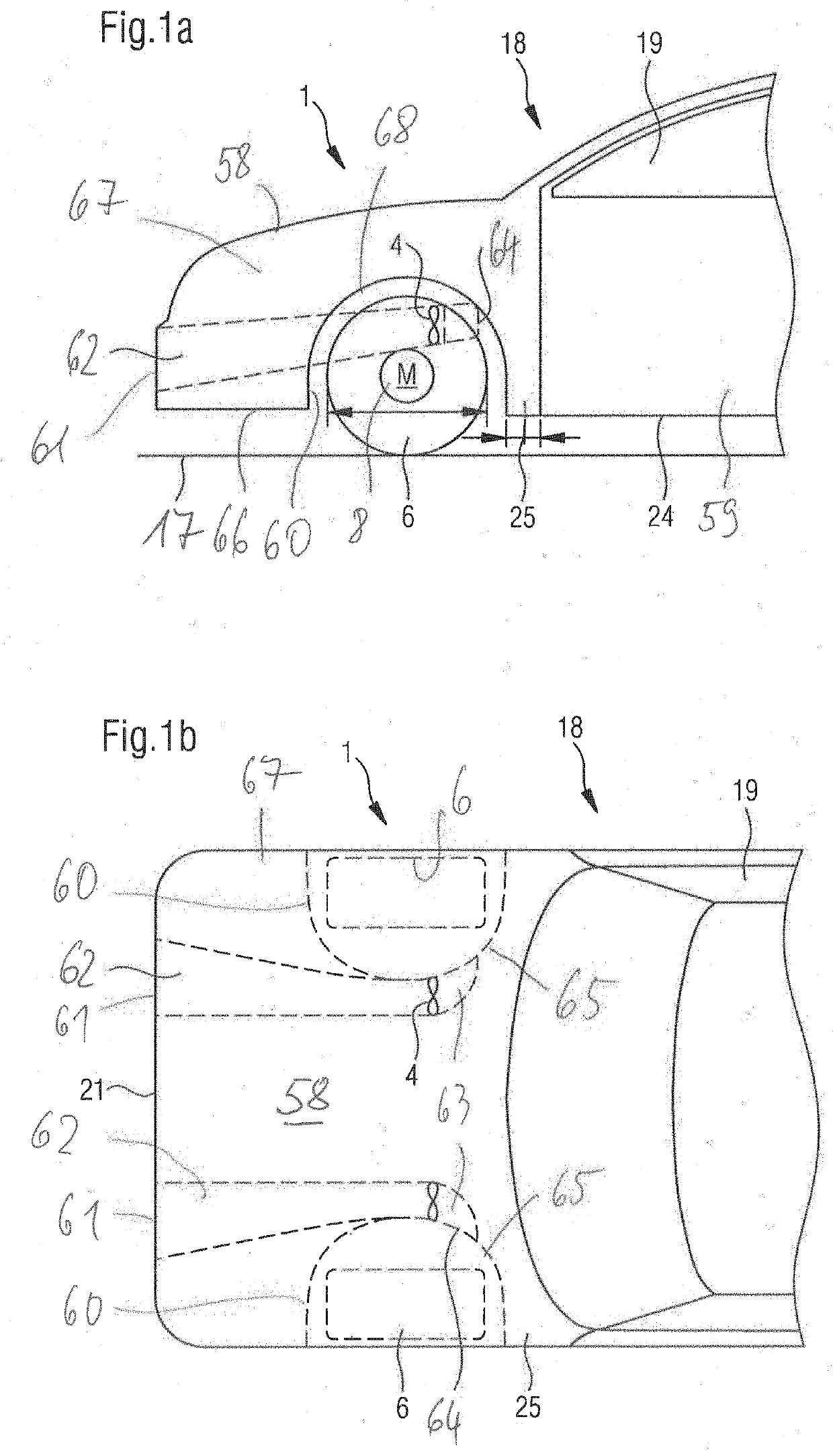
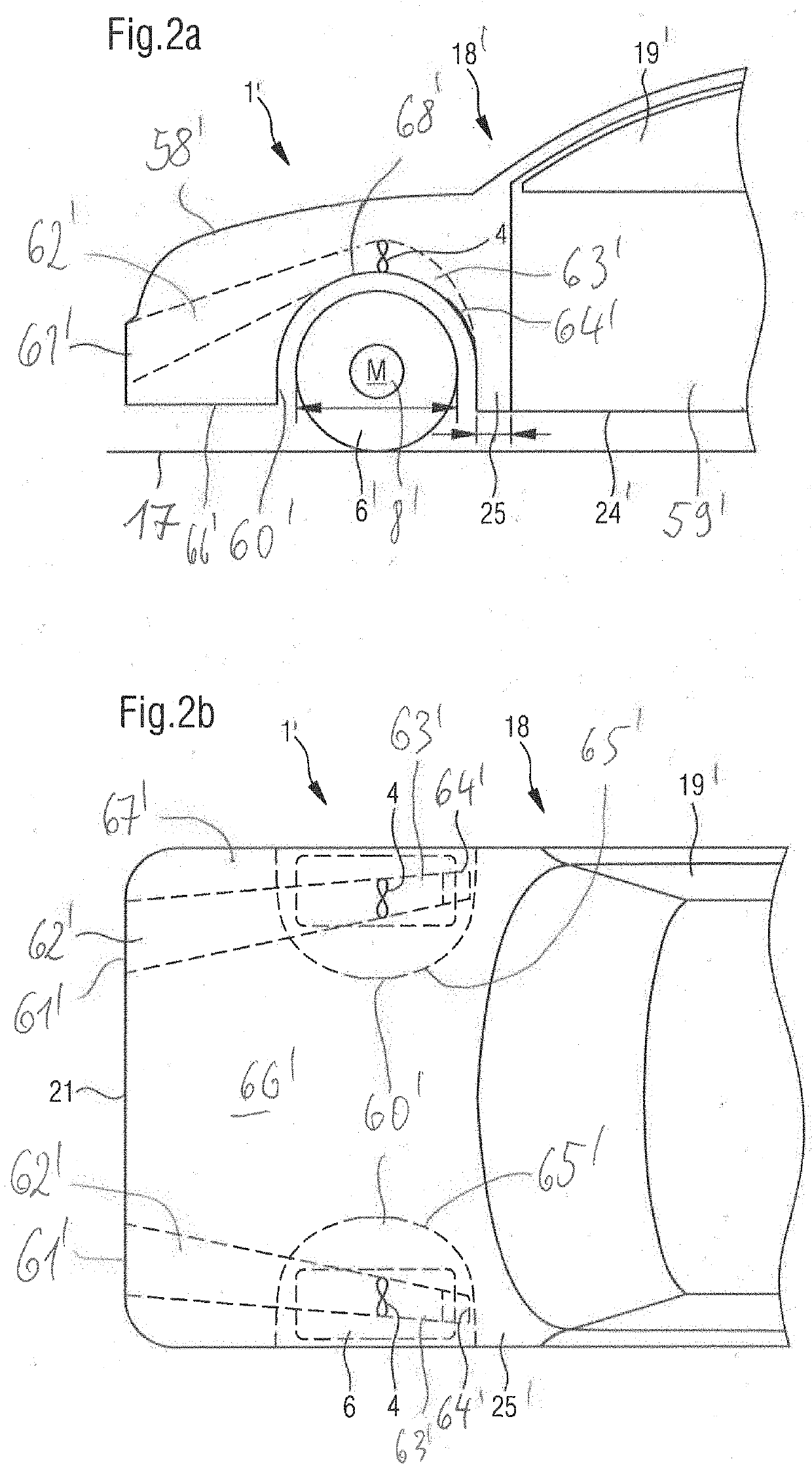
[0084]As can be seen in the drawing, the wind generator 1, 1′, 1(3), 1(4) is situated onboard a vehicle 18 that is suitable for roadway travel, whereby this vehicle 18 is able to generate current from its kinetic energy, for example during a braking operation. For this purpose, such a wind generator 1, 1′, 1(3) is preferably situated within the vehicle body 25, for example beneath the hood 58, and therefore has no negative effect on the air resistance of the road vehicle 18.

[0085]The wind generator 1, 1′, 1(3) may be permanently active, or, when necessary, may be switched on as soon as excess kinetic energy is available, such as during a braking operation or during downhill travel. For this purpose, the wind generator 1, 1′, 1(3) may be concealed behind a streamlined cowling which may be opened as needed, but which can be closed during acceleration operations or if a maximum travel speed is desired, in order not to generate any air resistance.

[0086]FIG. 1a shows the wind power plant...


PUM


Abstract

The invention refers to a wind generator onboard of a road vehicle, the wind generator comprising: at least one wind wheel which is mounted onboard of a road vehicle to be rotatable around a rotational axis, the at least one wind wheel comprising at least one or more blade configured to convert flow energy of wind into rotational energy, at least one generator, the at least one generator being coupled to a hub or shaft of the at least one wind wheel or to an output shaft of a gear connected the at least one wind wheel, the at least one generator being configured to convert the rotational energy into electrical energy, wherein a center of gravity of the wind wheel, together with a hub and rotor shaft and rotatable parts of the generator or of the gear which are coupled to the hub or rotor shaft and rotate around the same rotational axis, is translationally movable in a horizontal or approximately horizontal direction together with the road vehicle in the direction of travel, wherein the at least one generator is either a direct current generator or is an alternating current generator with an output side of the at least one generator being coupled to a rectifier so as to provide the electrical energy as a direct current output, wherein at least one energy storage is coupled to the direct current output of the at least one generator or to the direct current output of the rectifier, for receiving and storing the electrical energy, wherein the extension of the at least one wind wheel parallel to its rotational axis is smaller than the extension of the at least one wind wheel transversely to its rotational axis, wherein, in the direction of travel of the road vehicle, there is no cascade of more than one wind wheel, i.e. no two wind wheels are arranged behind each other, and wherein the shape and size of the body of the vehicle are neither modified or increased by the wind generator nor affected by extensions fixed to the body of the vehicle housing the wind generator.

Description

REFERENCE TO PENDING PRIOR PATENT APPLICATIONS[0001]This patent application:[0002](i) is a continuation-in-part of pending prior U.S. patent application Ser. No. 16 / 385,085 filed at Apr. 16, 2019 by Jan Franck for a TRANSLATIONALLY MOVEABLE WIND POWER PLANT (Attorney's Docket No. KUCH-81 CIP), which patent application, in turn:[0003](1) is a continuation-in-part of prior U.S. patent application Ser. No. 15 / 504,860 filed at Feb. 17, 2017 by Jan Franck for WIND TURBINE WHICH CAN BE MOVED IN TRANSLATION (Attorney's Docket No. KUCH-81), which patent application, in turn,[0004](a) is a 371 national stage entry of International (PCT) Patent Application No. PCT / IB2015 / 001384, filed Aug. 18, 2015 by Jan Frank for WIND TURBINE WHICH CAN BE MOVED IN TRANSLATION, which patent application, in turn, claims benefit of German Patent Application No. DE 10 2014 012 048.1, filed Aug. 18, 2014.[0005]The four (4) above-identified patent applications are hereby incorporated herein by reference.FIELD OF ...

Claims


Application Information

Patent Timeline
Patent Type & Authority Applications(United States)
IPC IPC(8): F03D9/32F03D9/25B60L8/00F03D9/19B60L53/54B60L53/52
CPCF03D9/32F03D9/25B60L8/006B60L2210/46B60L53/54B60L53/52F03D9/19F03D9/11F05B2240/941Y02E10/70Y02E10/72Y02E10/728Y02E70/30F05B2220/61B60L50/16B60L50/60B60L50/70B60L50/75Y02E60/36Y02T10/70Y02T10/7072Y02T90/12Y02T90/40
Inventor FRANCK, JAN
Owner FRANCK JAN
Why Eureka
Try Eureka