Device for boat propulsion or energy production
a propulsion device and energy production technology, applied in the field of propulsion devices, can solve the problems of obscuring the view, reducing the propulsion efficiency, and further increasing the negative effects of the above mentioned, and achieve the effects of improving the propulsion device of boats, reducing air resistance, and reducing energy consumption
- Summary
- Abstract
- Description
- Claims
- Application Information
AI Technical Summary
Benefits of technology
Problems solved by technology
Method used
Image
Examples
first embodiment
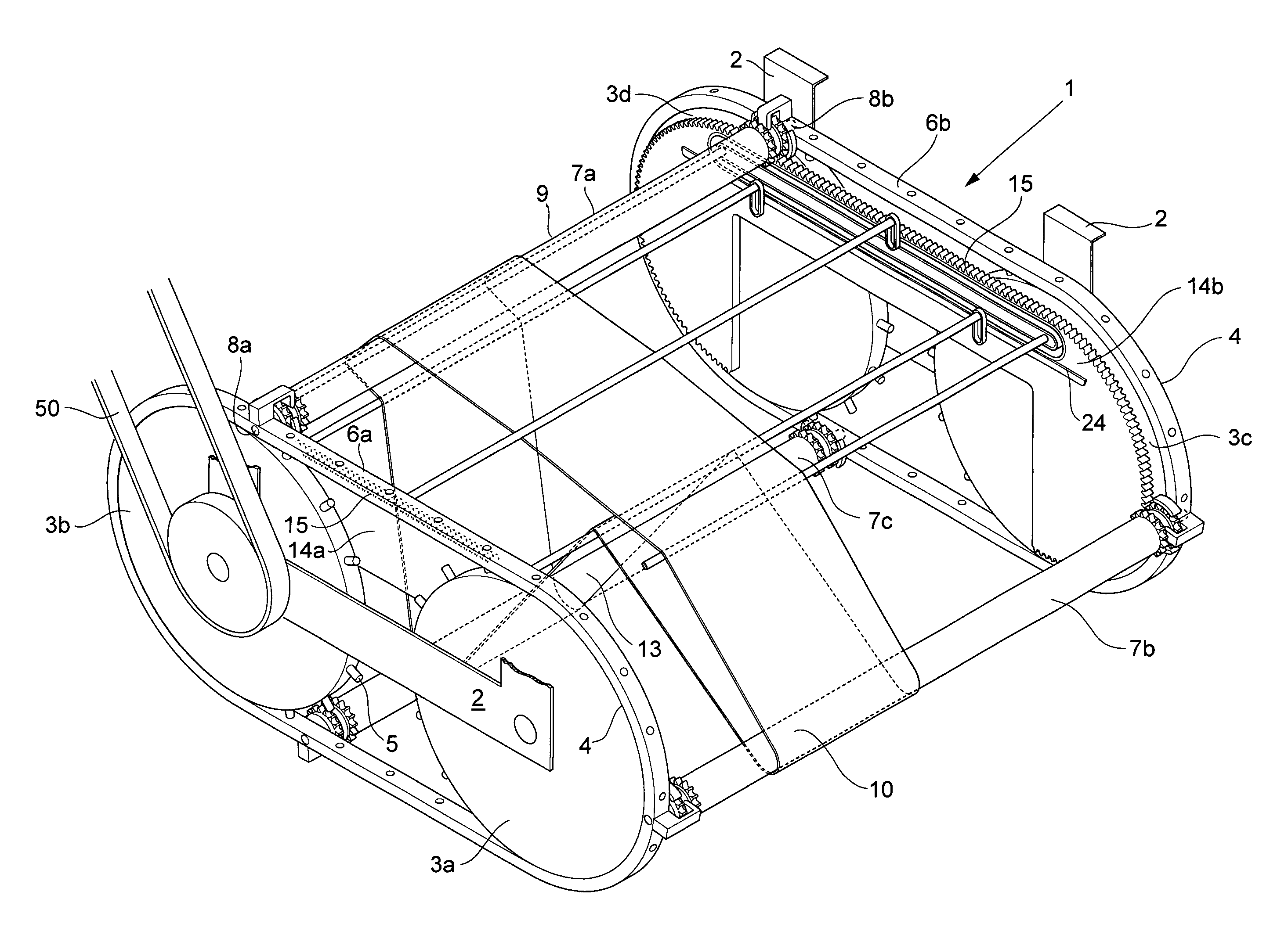
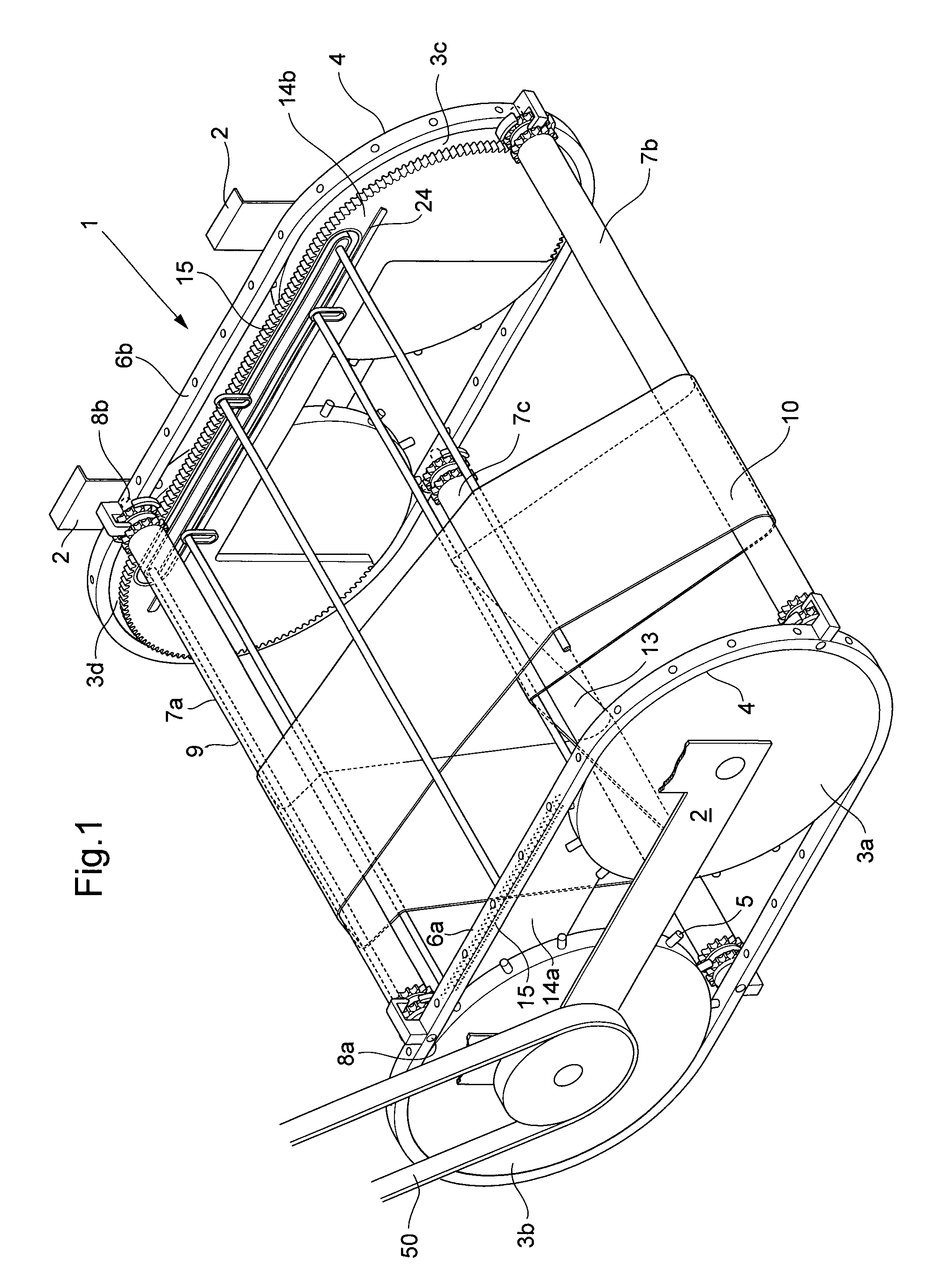
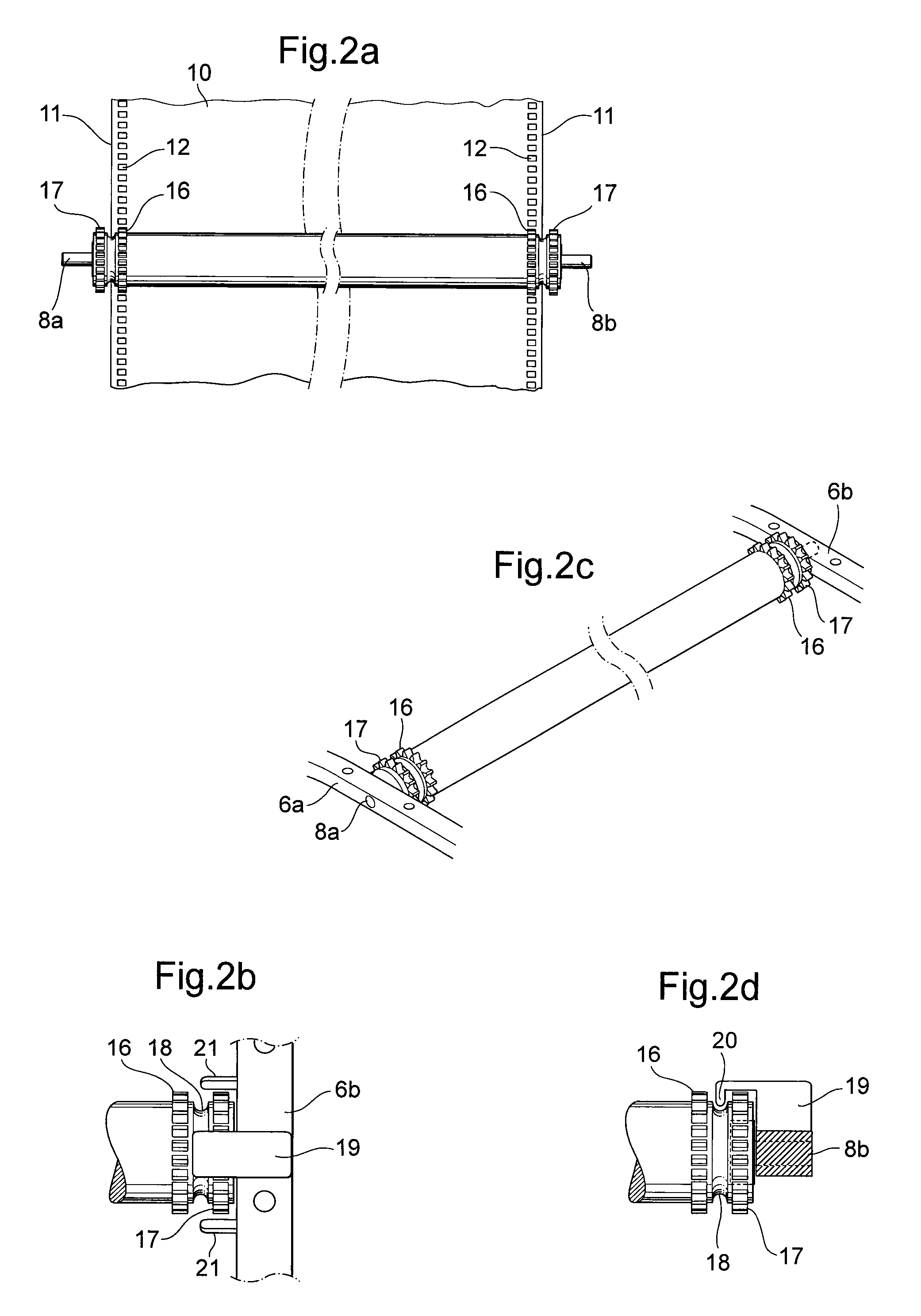
[0050]FIG. 1 shows schematically a perspective view of the invention according to the invention, wherein the propulsion device 1 comprises a frame 2, four driving wheels 3a-d with a peripheral surface 4 and friction devices 5, which are rotatably arranged in the frame 2. The friction devices according to the Figure are preferably comprised by protrusions, but also other type of friction devices are possible. In the Figure, two of the driving wheels 3a, 3b constitute a first set of driving wheels and the other two driving wheels 3c, 3d parallel to the two driving wheels a second set of driving wheels. A set of driving wheels can comprise one or a plurality of driving wheels. A first track 6a is arranged on the first set of driving wheels such that the track is arranged in contact with the friction devices on the periphery of the driving wheels. A second track 6b is arranged on the second set of driving wheels such that the track is arranged in contact with the friction devices on the...
second embodiment
[0058]FIG. 6a shows schematically a view of a device according to the invention in a first position. The device comprises two sets of driving wheels 3 of one driving wheel, each rotatably arranged in a frame 2, four shovel rollers 7a-d being rotatably arranged in the periphery of the driving wheel in a track 6 integrated with the driving wheel, a carpet feeding device fixedly arranged in the frame having a part-length corresponding to a part of the periphery of the driving wheel 3 arranged with a tooth receiving surface 15, in such manner that at most between two and three shovel rollers 7a-d are in a position such that their tooth devices 17 meshes with the tooth receiving surface 15 of the carpet feeding device 14 such that the shovel rollers 7a-d are brought to rotate. The Figure shows a first shovel surface 13a and a second shovel surface 13b.
[0059]FIG. 6b-c shows schematically side views of the second embodiment in a second and third position where the shovel surfaces are brou...
third embodiment
[0062]FIG. 8a-c shows schematically a view of a third embodiment according to the invention in a first position to a third position according to a similar description as disclosed in FIG. 6a-c but where the tooth receiving surface 15 of the carpet feeding device 14b corresponds to between 25-50% of the periphery of the driving wheel. This length is adapted to correspond to the distance where the carpet-like device 10 is shaped to a shovel and is thus minimized to reduce the friction and thus the energy required for driving the device 1. The Figure shows an alternative embodiment of the frame roller fastener, with the purpose to achieve a further improved stretching of the carpet-like device. These essentially cylinder-shaped frame rollers extend, via an arm with an angle for allowing passage of a slide mount between the frame roller and the carpet feeding device, from a first frame roller fastener arranged inside the trolley track arranged on a first carpet feeding device 14a via an...
PUM
 Abstract
Description
Claims
Application Information
 - R&D
- Intellectual Property
- Life Sciences
- Materials
- Tech Scout
- Unparalleled Data Quality
- Higher Quality Content
- 60% Fewer Hallucinations
Browse by: Latest US Patents, China's latest patents, Technical Efficacy Thesaurus, Application Domain, Technology Topic, Popular Technical Reports.
© 2025 PatSnap. All rights reserved.Legal|Privacy policy|Modern Slavery Act Transparency Statement|Sitemap|About US| Contact US: help@patsnap.com


