Device for boat propulsion or energy production

a propulsion device and boat technology, applied in the direction of marine propulsion, machine/engine, vessel construction, etc., can solve the problems of reducing propulsion efficiency, obscuring view, and further negative effects, so as to improve the propulsion device of boats, energy efficient, and minimize the effect of air resistan

Active Publication Date: 2013-08-08
COSMOMIND
View PDF2 Cites 0 Cited by
  • Summary
  • Abstract
  • Description
  • Claims
  • Application Information

AI Technical Summary

Benefits of technology

[0005]An object of the present invention is to improve the propulsion device of boats, preferably boats of smaller type such as pedalos for recreational use, smaller fishing boats for recreational fishing and other vessels. The invention enables propulsion of boats in a more energy efficient manner compared to previous solutions for pedalos, for instance of paddle wheel type. Further, the invention enables that the propulsion device can be placed essentially under water. This enables that no already limited space in the boat is taken up by a paddle wheel or obscures the view, that the air resistance is minimized and that the propulsion device is less sensitive to heavy seas. Moreover, the invention will enable a more silent propulsion than normal paddle wheel propelled vessels due to the placement of the device below the water level.
[0018]A second objective of the invention is to enhance a device for energy production, preferably from wind, wave power and flowing water. The invention can be used for extracting energy from wind power and can unlike the existing technology be used in strong winds above 25 meters / second without risk for failure, and where a possible failure have very limited negative consequences, compare for instance a loss of a rotor blade with a destroyed carpet-like device. The device according to the invention can further be manufactured with large dimensions, with a large wind capturing carpet-like device to be able to extract more energy and can moreover be adjusted by changing the angle to the wind as needed and thereby increase the efficiency even further. Unlike so-called fast runners the device according to the invention further generate considerably less vibrations which makes it suitable to use on for instance rooftops.
[0019]When using a device according to the invention for extracting energy from flowing water, the freedom of placing the device is considerable unlike the known technology. The device can be placed entirely under the water level such as e.g. close to the seabed and be fastened there since no protruding shovels exist that move in a direction opposite the flow direction. Thereby the negative effects that a device in a sea environment could have as being an obstacle for boat traffic or for purely esthetical reasons are eliminated. Damage to fish and other living creatures is further minimized.
[0020]The device according to the invention, placed on the water surface, can further extract energy even from smaller 1-3 meter waves which is an advantage compared to the wave power technologies of today.

Problems solved by technology

This is partly due to the upper paddles direction of movement but also due to the increased friction in the water.
Further, the part of the paddle wheel that is above the water level takes up space in the boat in an already limited space, alternatively obscures the view if the paddle wheels are located on the sides of the boat.
This part will further act as an air hole and substantially increase the air resistance of the boat in an environment that is windy and thus decrease the propulsion efficiency.
Since this type of propulsion device requires that the paddle wheel size increases if an increased propulsion speed is desirable the above mentioned negative effects will increase further.
Boats with paddle wheel propulsion are also sensitive for heavy seas.
High waves will lead to that a larger share of the paddles is located above the water level which will further decrease the propulsion efficiency.
The drawback of existing solutions for energy production through wind power plants is that these are so-called fast runners which must be stopped at strong winds in order not to risk failure through loss of the rotor blades.

Method used


Image

  • Device for boat propulsion or energy production
  • Device for boat propulsion or energy production
  • Device for boat propulsion or energy production

Examples


first embodiment

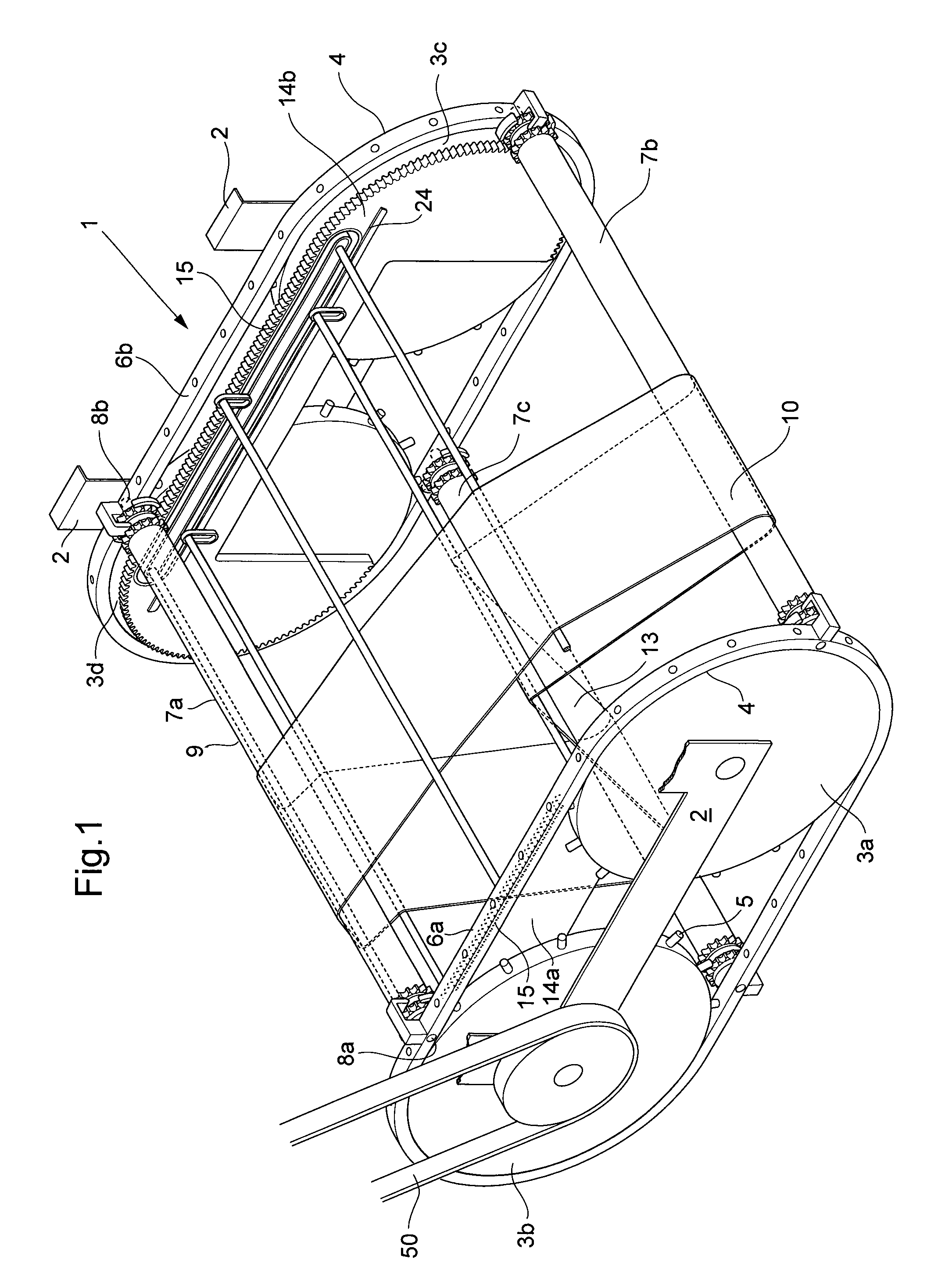
[0060]FIG. 1 shows schematically a perspective view of the invention according to the invention, wherein the propulsion device 1 comprises a frame 2, four driving wheels 3a-d with a peripheral surface 4 and friction devices 5, which are rotatably arranged in the frame 2. The friction devices according to the Figure are preferably comprised by protrusions, but also other type of friction devices are possible. In the Figure, two of the driving wheels 3a, 3b constitute a first set of driving wheels and the other two driving wheels 3c, 3d parallel to the two driving wheels a second set of driving wheels. A set of driving wheels can comprise one or a plurality of driving wheels. A first track 6a is arranged on the first set of driving wheels such that the track is arranged in contact with the friction devices on the periphery of the driving wheels. A second track 6b is arranged on the second set of driving wheels such that the track is arranged in contact with the friction devices on the...

second embodiment

[0068]FIG. 6a shows schematically a view of a device according to the invention in a first position. The device comprises two sets of driving wheels 3 of one driving wheel, each rotatably arranged in a frame 2, four shovel rollers 7a-d being rotatably arranged in the periphery of the driving wheel in a track 6 integrated with the driving wheel, a carpet feeding device fixedly arranged in the frame having a part-length corresponding to a part of the periphery of the driving wheel 3 arranged with a tooth receiving surface 15, in such manner that at most between two and three shovel rollers 7a-d are in a position such that their tooth devices 17 meshes with the tooth receiving surface 15 of the carpet feeding device 14 such that the shovel rollers 7a-d are brought to rotate. The Figure shows a first shovel surface 13a and a second shovel surface 13b.

[0069]FIG. 6b-c shows schematically side views of the second embodiment in a second and third position where the shovel surfaces are brou...

third embodiment

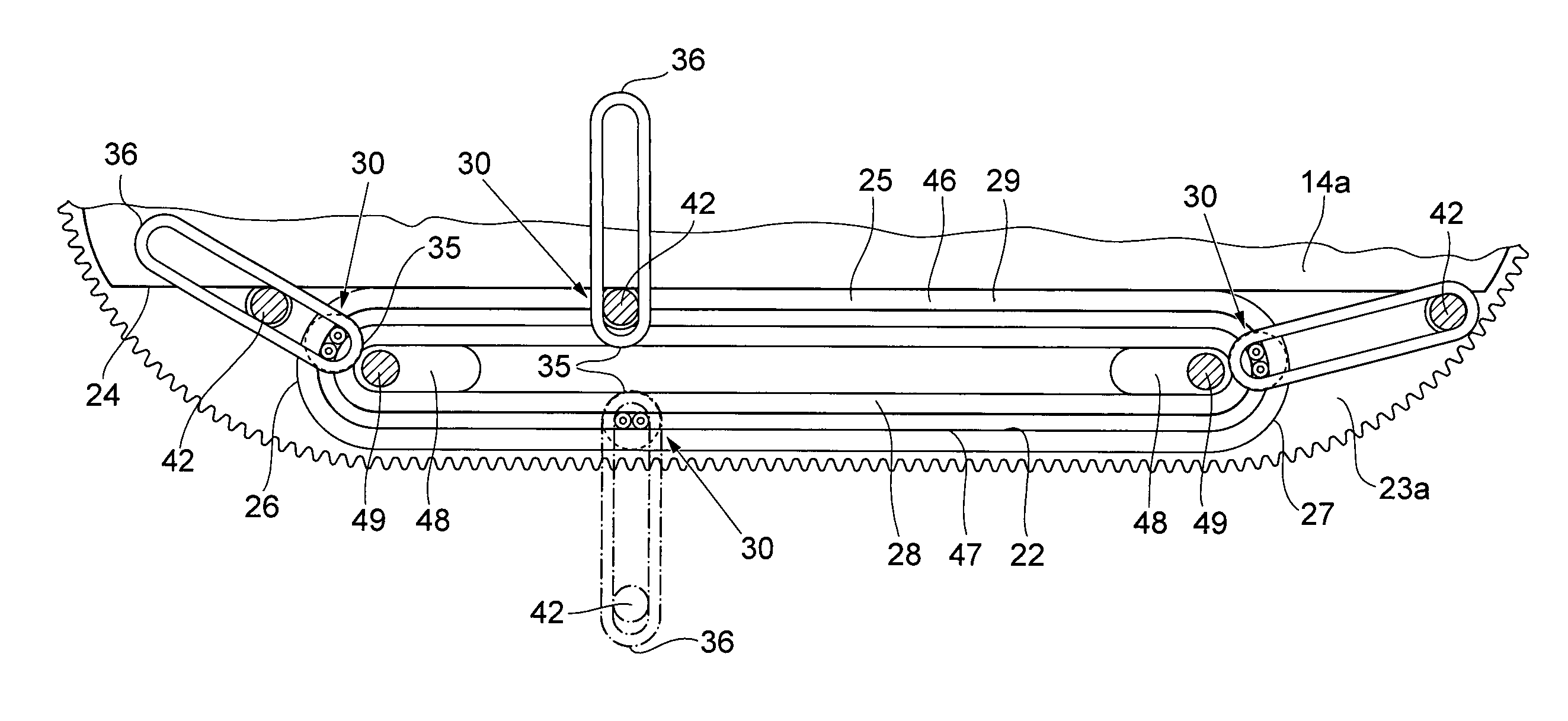
[0072]FIG. 8a-c shows schematically a view of a third embodiment according to the invention in a first position to a third position according to a similar description as disclosed in FIG. 6a-c but where the tooth receiving surface 15 of the carpet feeding device 14b corresponds to between 25-50% of the periphery of the driving wheel. This length is adapted to correspond to the distance where the carpet-like device 10 is shaped to a shovel and is thus minimized to reduce the friction and thus the energy required for driving the device 1. The Figure shows an alternative embodiment of the frame roller fastener, with the purpose to achieve a further improved stretching of the carpet-like device. These essentially cylinder-shaped frame rollers extend, via an arm with an angle for allowing passage of a slide mount between the frame roller and the carpet feeding device, from a first frame roller fastener arranged inside the trolley track arranged on a first carpet feeding device 14a via an...


PUM


Abstract

Propulsion device for boats or device or energy production comprising: a first track (6a) a second track (6b); driving wheels (3a-d) each having a peripheral surface (4) comprising a friction device (5) rotatably arranged in at least one frame (2), wherein the first track (6a) is arranged in contact with the friction devices (5) at a first set of driving wheels (3a, b), the second track (6b) is arranged in contact with the friction devices (5) at a second set of driving wheels (3c, d), such that the tracks move with the same speed as the peripheral surface of the rotatable driving wheels where the track is in contact with the friction devices when the driving wheels rotate; a plurality of shovel rollers (7a-d) each comprising a first (8a) and a second end (8b) and between the ends a device (9) with an outer periphery, wherein the first ends (8a) of the shovel rollers are arranged in the first track (6a) and the second ends (8b) of the shovel rollers are arranged in the second track (6b) such that the shovel rollers move with the tracks in relation to the structure when the driving wheels rotate, wherein the device further comprises a flat continuous carpet-like device (10) with side-ends (11) which is arranged between the first and second sets of driving wheels and abutting the outer periphery of the shovel rollers (7a-d); that the carpet-like device forms a shovel surface (13) between two of the shovel rollers (7a-d), and that the formed shovel moves in relation to the frame when the shovel rollers (7a-d) move in relation to the frame.

Description

TECHNICAL FIELD[0001]The present invention relates generally to a propulsion device for boats in a first embodiment.[0002]The present invention relates generally to a device for energy production in a second embodiment.BACKGROUND ART[0003]It is known to use propulsion devices of rotating paddle wheel type for boats, e.g. pedalos for recreational use, smaller fishing boats for recreational fishing or other light vessels. To maximize the propulsion efficiency such devices requires that the propulsive paddle wheels are located to at least 50% above water level. If a larger share of the paddle wheel is located below the water level the opposing force, in a direction opposite the direction of movement, will increase. This is partly due to the upper paddles direction of movement but also due to the increased friction in the water. Further, the part of the paddle wheel that is above the water level takes up space in the boat in an already limited space, alternatively obscures the view if t...

Claims


Application Information

Patent Timeline
Patent Type & Authority Applications(United States)
IPC IPC(8): B63H5/03
CPCB63H1/04B63H5/02B63H5/03Y02B10/30Y02E10/28F03B17/066Y02E10/20Y02E10/70F03B9/00F03B13/18F03B17/068F03D5/00
Inventor GIDLUND, PER
Owner COSMOMIND
Why Eureka
Try Eureka