Continuous self-test in capacitive sensor

a capacitive sensor and self-testing technology, applied in the field of microelectromechanical devices, can solve the problems of complex implementation, power consumption and complex power consumption of dc test signals, and cannot be used during normal operation

Active Publication Date: 2016-07-14
MURATA MFG CO LTD
View PDF1 Cites 15 Cited by
  • Summary
  • Abstract
  • Description
  • Claims
  • Application Information

AI Technical Summary

Benefits of technology

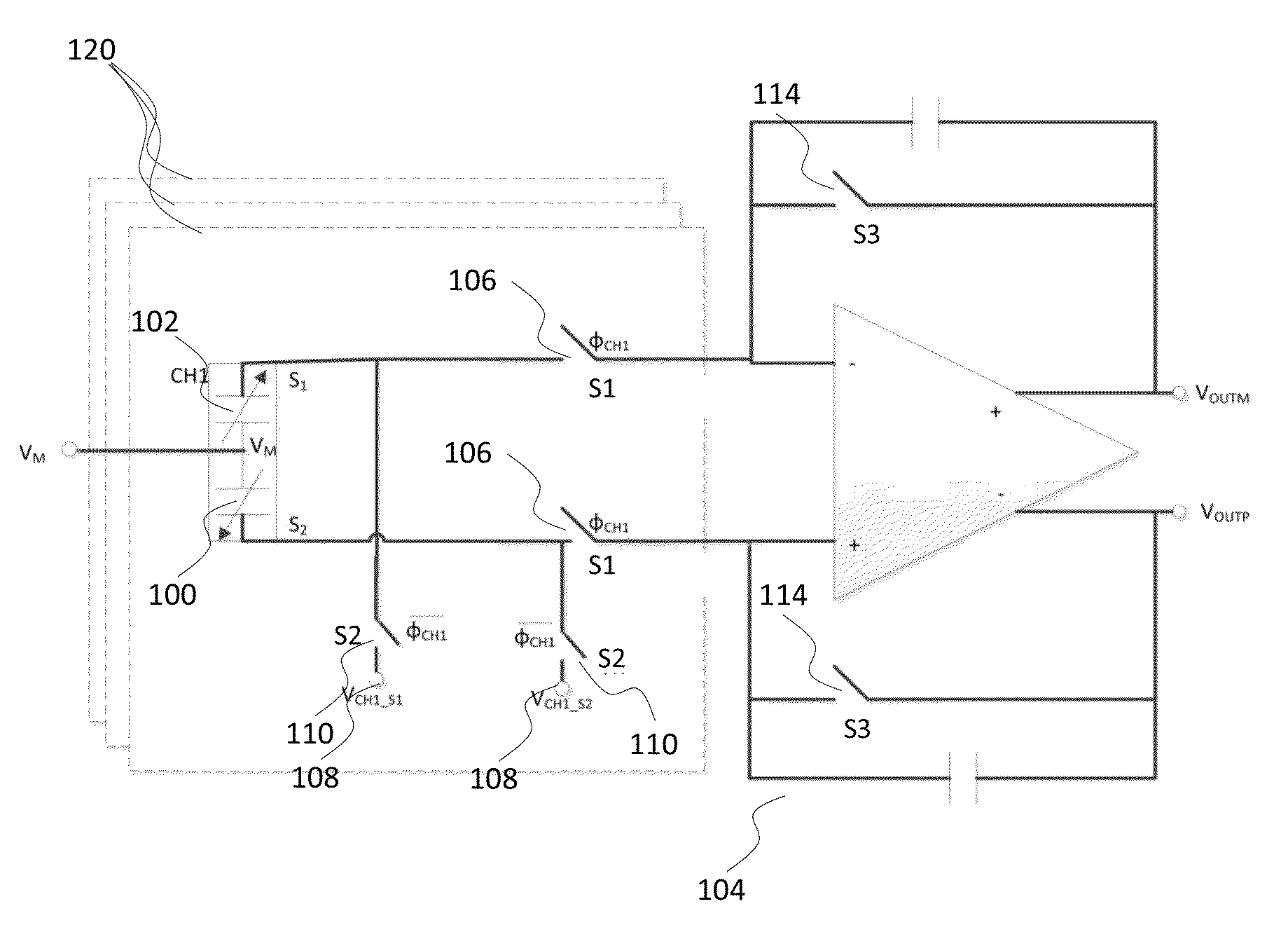
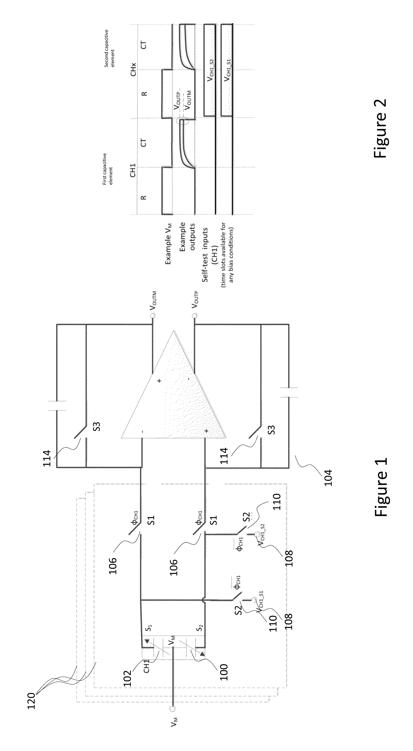
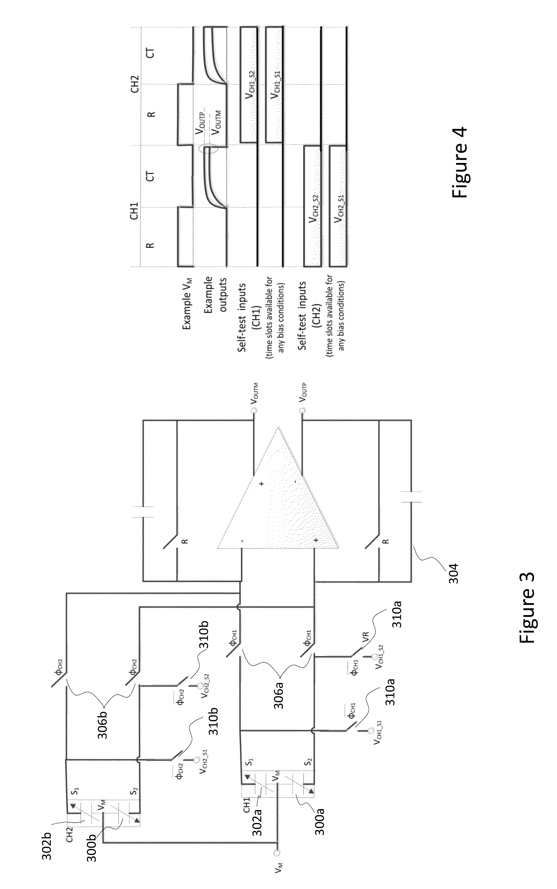
[0013]An object of the present invention is to provide for a capacitive sensor a local self-test capability that avoids or at least alleviates at least one of the above challenges.
[0015]Embodiments of the present invention have the advantage that self-testing functionality may be continuous, and it causes minimal parasitic effects and minimal additional area consumption especially in the analog parts of the circuitry.

Problems solved by technology

The DC test signal cannot however be used during normal operation, since there is no way of making difference between self-test response and real inertial acceleration.
This solution, however, requires wide band amplifiers and an additional demodulation stage, making the implementation power consuming and complex.

Method used


Image

  • Continuous self-test in capacitive sensor
  • Continuous self-test in capacitive sensor
  • Continuous self-test in capacitive sensor

Examples


Embodiment Construction

[0065]The following embodiments are exemplary. Although the specification may refer to “an”, “one”, or “some” embodiment(s), this does not necessarily mean that each such reference is to the same embodiment(s), or that the feature only applies to a single embodiment. Single features of different embodiments may be combined to provide further embodiments.

[0066]As used herein, the term “circuitry” refers to all of the following: (a) hardware-only circuit implementations, such as implementations in only analog and / or digital circuitry, wherein the circuitry may comprise discrete and / or integrated components, and (b) combinations of circuits and software (and / or firmware), such as (as applicable): (i) a combination of processor(s) or (ii) portions of processor(s) / software including digital signal processor(s), software, and memory(ies) that work together to cause an apparatus to perform various functions, and (c) circuits, such as a microprocessor(s) or a portion of a microprocessor(s),...


PUM


Abstract

A capacitive sensor device includes capacitive elements for detecting at least two inertial channels. At least one of the inertial channels comprises at least two self-test tones with distinctive fundamental frequencies. Inertial signals in the at least two inertial channels are caused by change of capacitance in the capacitive elements due to movements of rotor masses. Self-test tones are fed into at least one capacitive element under control of a self-test control module and the at least two inertial channels are temporally multiplexed to allow feeding of the self-test tones during normal operation of the capacitive sensor device. Signals in the inertial channels are processed for extracting self-test signals corresponding to the self-test tones, and the self-test signals are analyzed for self-test purposes. Alarm is triggered if multiple consecutive samples of predefined set of self-test signals indicate error with same polarity.

Description

BACKGROUND[0001]1. Field[0002]The present invention relates to microelectromechanical devices and specifically to an inertial sensor with self-test capability and a self-test method for an inertial sensor.[0003]2. Description of the Related Art[0004]Micro-Electro-Mechanical Systems or MEMS can be defined as micro-scale mechanical and electro-mechanical systems where at least some elements have a mechanical functionality. MEMS structures can be applied to quickly and accurately detect very small changes in physical properties.[0005]Capacitive microelectromechanical sensors have become part of many consumer devices and they are used also in a variety of safety critical applications, such as electronic stability control (ESC). Especially in the safety related applications, it is important to identify potential failures in mechanical or electrical signal paths of the capacitive sensor.[0006]A capacitive sensor comprises at least one microelectromechanical element that comprises at least...

Claims


Application Information

Patent Timeline
Patent Type & Authority Applications(United States)
IPC IPC(8): G01P21/00G01P15/125
CPCG01P15/125G01P21/00G01C25/00G01D5/24G01D18/00G01D2218/10G01P15/08G01C19/5755G01R31/3187B81B7/02
Inventor AALTONEN, LASSESALO, TEEMU
Owner MURATA MFG CO LTD
Why Eureka
Try Eureka