Display mounting system and method

a technology of display and mounting system, which is applied in the direction of signs, instruments, manufacturing tools, etc., can solve the problems of user frustration, difficulty in opening the gripper, and the possibility of falling or other injuries

Inactive Publication Date: 2016-07-14
K INT
View PDF3 Cites 10 Cited by
  • Summary
  • Abstract
  • Description
  • Claims
  • Application Information

AI Technical Summary

Benefits of technology

[0012]The present invention, according to certain embodiments, provides a secure and easy-to-use system and method for mounting and un-mounting signs and displays that permit the signs or displays to be mounted on a ceiling, wall, or window frame while the person remains standing on the floor. The system and method may use a pole-mounted gripper to position a sign or display holding and mounting apparatus at a ceiling, wall, or window frame and to remove the sign or display holding and mounting apparatus from the ceiling, wall, or window frame. The gripper is easy to operate to an open position to release the sign or display holding and mounting apparatus at a mounting location and to engage the sign or display holding and mounting apparatus for removal from the mounting location.
[0013]The sign or display holding and mounting apparatus may include an elongated channel or holes for holding block-end hooks, hanger clips, or other mounting hardware. The elongated channel of certain embodiments includes grip enhancing portions that are engaged by the pole end gripper to prevent slipping of the elongated channel in the gripper. Slipping of the elongated channel in the pole end gripper is further enhanced by end caps that are mounted on the ends of the elongated channel. The end caps also block the ends of the channel to reduce the chance that a block-end hook or other hardware mounted in the channel will slip from the channel.
[0019]The elongated channel may include a pivot to permit pivoting movement between an upper portion and a lower portion of the elongated channel. The elongated channel may thereby be rotated to a convenient viewing angle even if the ceiling grid or other structure from which the display is suspended is not at the desired angle.

Problems solved by technology

The risk of falling or other injury is a very real possibility, particularly if the ladder, box or crate is set on a wet or uneven floor, if the employee must reach beyond the safe limit of the ladder, or if other customers or displays are nearby so as to prevent an ideal positioning of the ladder, or simply if the employee is unsteady when climbing the ladder or atop the crate.
The gripper can be difficult to open as a result of high spring force on the gripper jaw and the configuration of the gripper.
This can result in frustration by the user, damage from the falling sign, and even a risk of injury.
Slipping of the block-end hooks in the channel may result in the sign or display becoming uneven or may even cause the sign or display to dislodge or fall.

Method used


Image

  • Display mounting system and method
  • Display mounting system and method
  • Display mounting system and method

Examples


Embodiment Construction

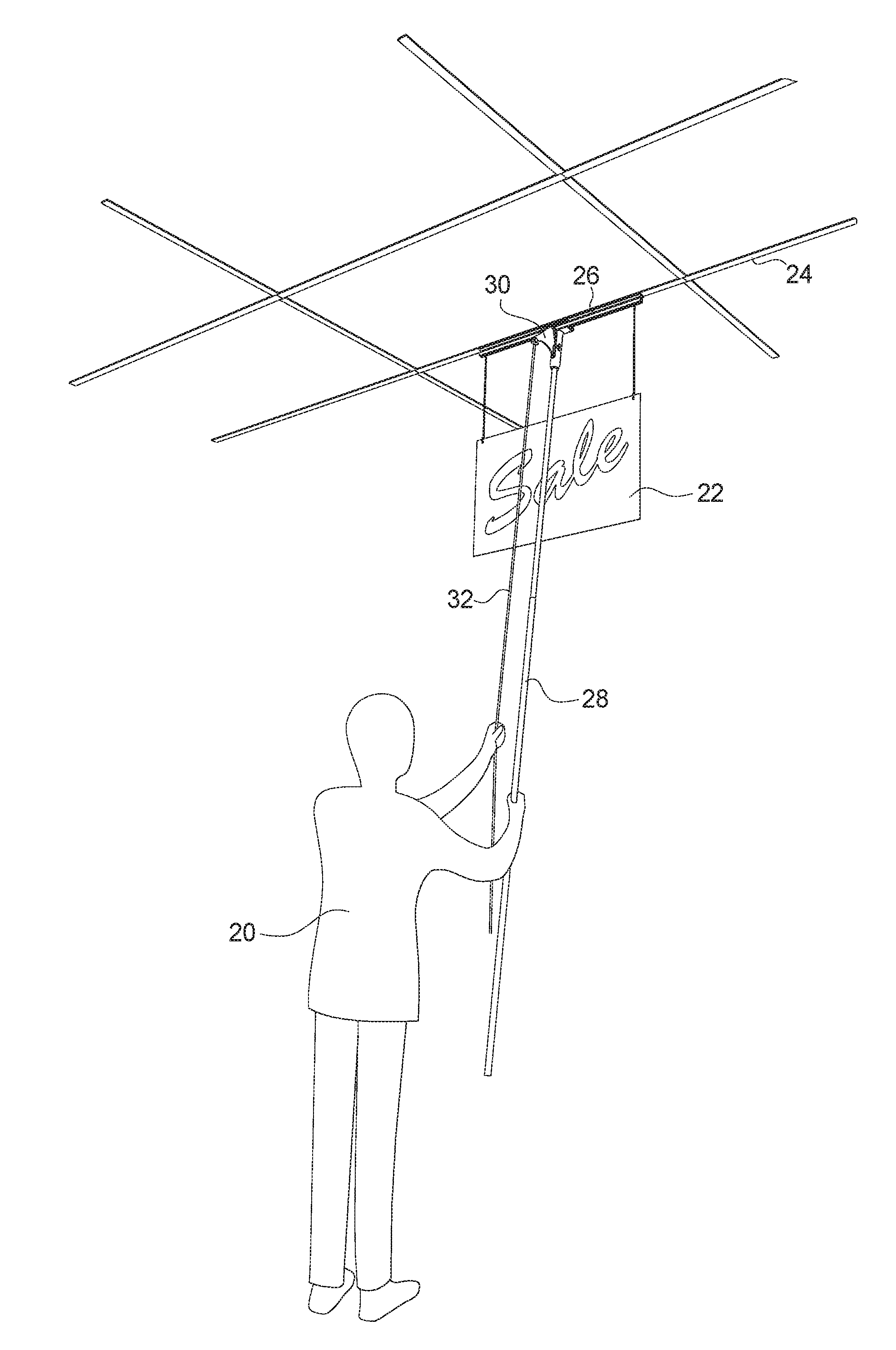
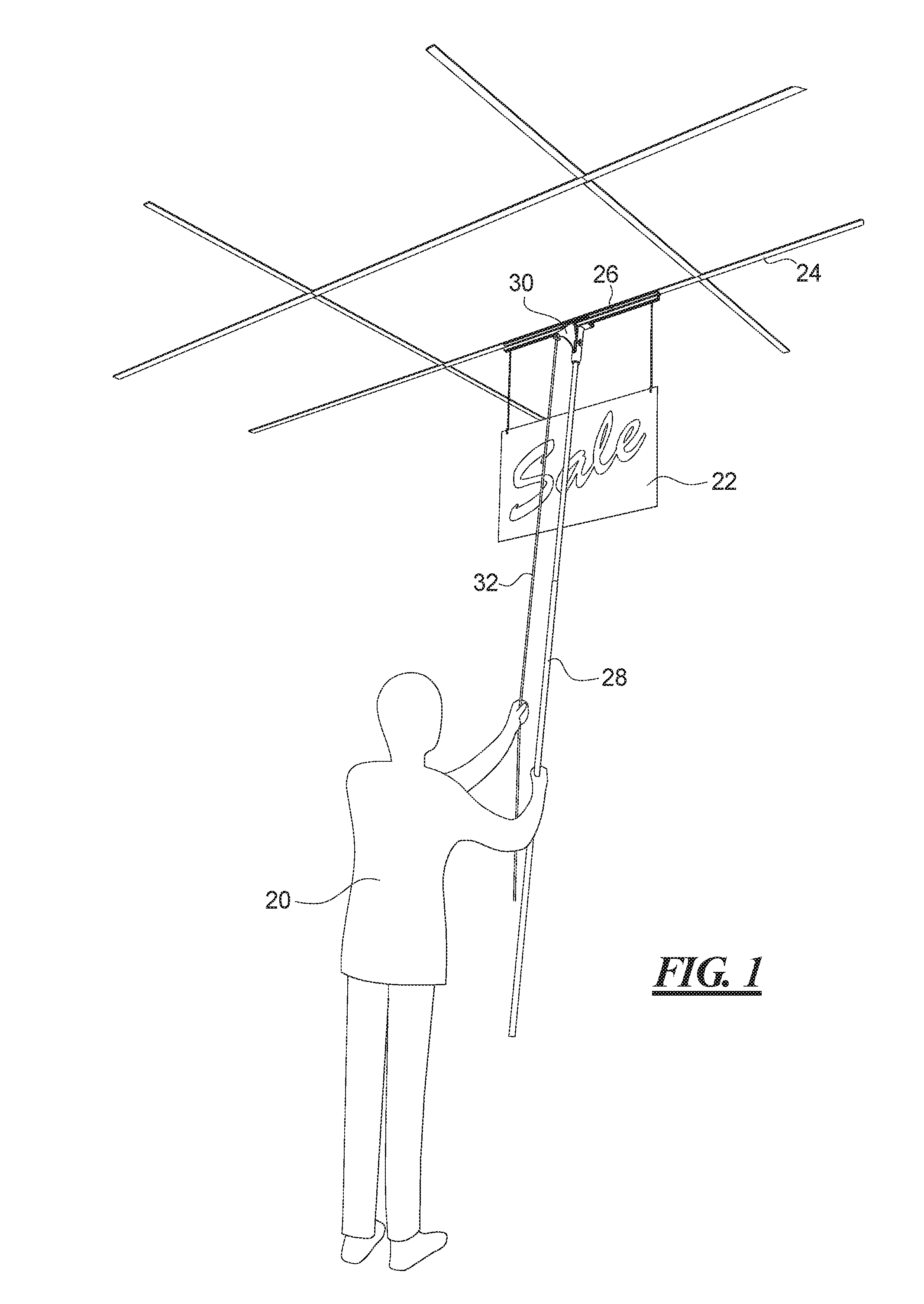
[0037]FIG. 1 shows a person 20 affixing a sign or other display 22 to a ceiling grid 24. The sign 22 is suspended from a holding and mounting channel 26 that may be affixed to metallic members of the ceiling grid 24 by magnets. The person 20 uses a pole 28 to position the channel 26 so that the channel 26 may magnetically engage the metallic members of the ceiling grid 24. The channel 26 is held at the end of the pole 28 by a pole end gripper 30. The person 20 may release the channel 26 from the pole end gripper 30 by pulling on a rope or cord 32 to release the channel 26 from the pole end gripper 30 and thereby leave the channel 26 affixed to the ceiling grid 24.

[0038]When the person 20 desires to take the sign or display 20 down from the ceiling, the person uses the pole 28 to position the pole end gripper 30 at the channel 26, operates the rope or cord 32 to engage the channel 26 with the pole end gripper 30, and moves the pole 28 away from the ceiling to thereby remove the chann...


PUM

PropertyMeasurementUnit
lengthaaaaaaaaaa
lengthsaaaaaaaaaa
lengthsaaaaaaaaaa

Abstract

A system and method for mounting a display or sign to a ceiling, wall or window frame includes an elongated channel having magnets that are affixed to a ceiling grid and mounting hooks or the like to suspend the sign or display from the channel. The channel includes high friction strips on a neck for engagement by a pole end gripper on a pole for mounting the channel on the ceiling while the user stands on the floor. End caps may be mounted on the channel. Mounting plates may be affixed to the ceiling or wall for magnetically engaging the channel. A wall mount channel includes an offset neck for gripping by the pole end gripper. A magnetic clip including a string for suspending a display may be mounted with the pole end gripper. An embodiment of the channel includes hooks for engaging an open girder ceiling.

Description

CROSS-REFERENCE TO RELATED APPLICATION[0001]This application is a divisional patent application of co-pending U.S. patent application Ser. No. 14 / 248,899, filed Apr. 9, 2014, which is incorporated herein by reference. This application claims the benefit of U.S. Provisional Patent Application Ser. No. 61 / 953,214, filed Mar. 14, 2014, which is incorporated herein by reference.BACKGROUND OF THE INVENTION[0002]1. Field of the Invention[0003]The present invention relates generally to a system and method for mounting a sign or display, and in particular to a magnetic or hook display mounting system and method.[0004]2. Description of the Related Art[0005]Signs and displays are used extensively in stores, theaters, shopping centers, recreational facilities, schools, tradeshows, restaurants, and other public places. Some signs are permanent signs to direct customers and others to locations within the facility, such as to exits or restrooms. However, temporary signs and displays are frequentl...

Claims


Application Information

Patent Timeline
Patent Type & Authority Applications(United States)
IPC IPC(8): G09F7/18
CPCG09F7/18G09F2007/186G09F2007/1852G09F2007/1847A47F13/06A47G1/1686B25B5/04B25B5/06E04B9/006G09F7/22Y10T29/49826B25J1/04
Inventor WHITE, MICHAEL J.
Owner K INT
Why Eureka
Try Eureka