Aeration device

a technology of aeration device and aeration chamber, which is applied in the direction of machines/engines, chemical/physical processes, and combustion gas purification/modification, etc., can solve the problem that the conventional aeration device cannot be used at a high depth under water, and achieve the effect of improving the air intake force, improving the amount of dissolved oxygen, and efficient aeration

Active Publication Date: 2016-07-21
JANG SUN WON
View PDF5 Cites 5 Cited by
  • Summary
  • Abstract
  • Description
  • Claims
  • Application Information

AI Technical Summary

Benefits of technology

[0035]According to the present invention, the aeration device can improve the air intake force so as to suck the water filled in the inflow pipe introducing air at the beginning of starting, thus performing the aeration efficiently even in deep water, can locate air bubbles discharged with the water in a downward direction, thus making the air stay under water for a long period of time, can mix the water and air mixed in the mixing unit again by means of the protrusions formed on the discharge unit, thus preventing the contact surfaces between the water and the air from being decreased during the discharging to increase the amount of dissolved oxygen, can control an amount of air introduced through the air adjusting valve, thus efficiently performing the aeration, and can increase the mixing rate between the water and the air, thus improving the aeration performance to allow aerobic microorganisms to be continuously cultivated and further to accelerate aerobic fermentation.

Problems solved by technology

Accordingly, the conventional aeration device cannot be used at a high depth under water.

Method used


Image

  • Aeration device
  • Aeration device
  • Aeration device

Examples


first embodiment

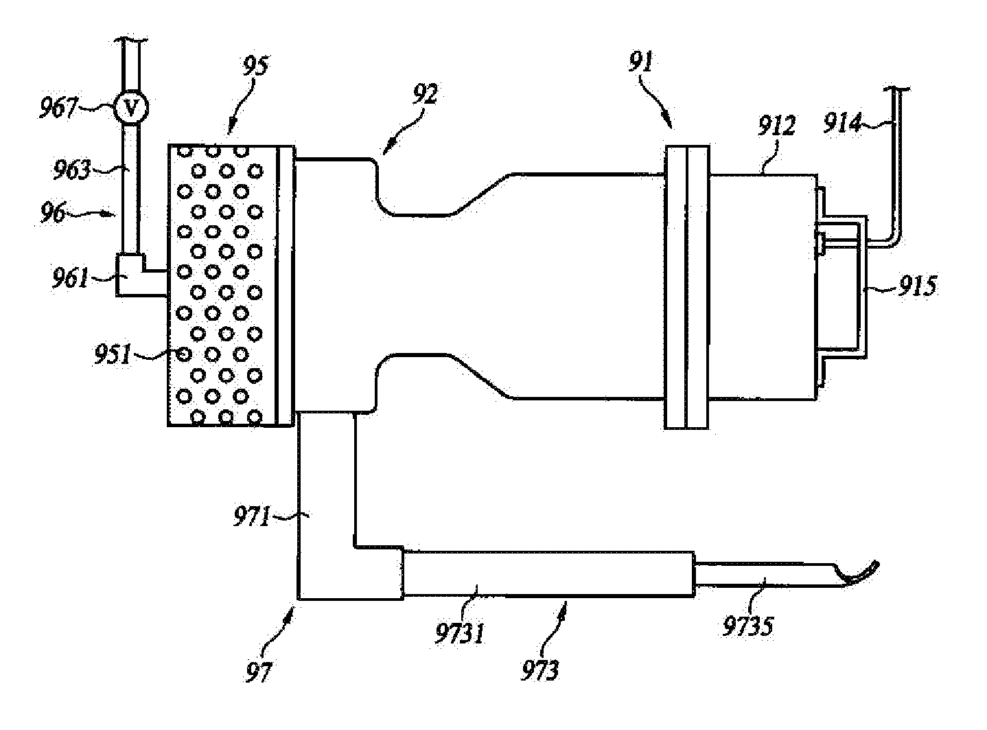
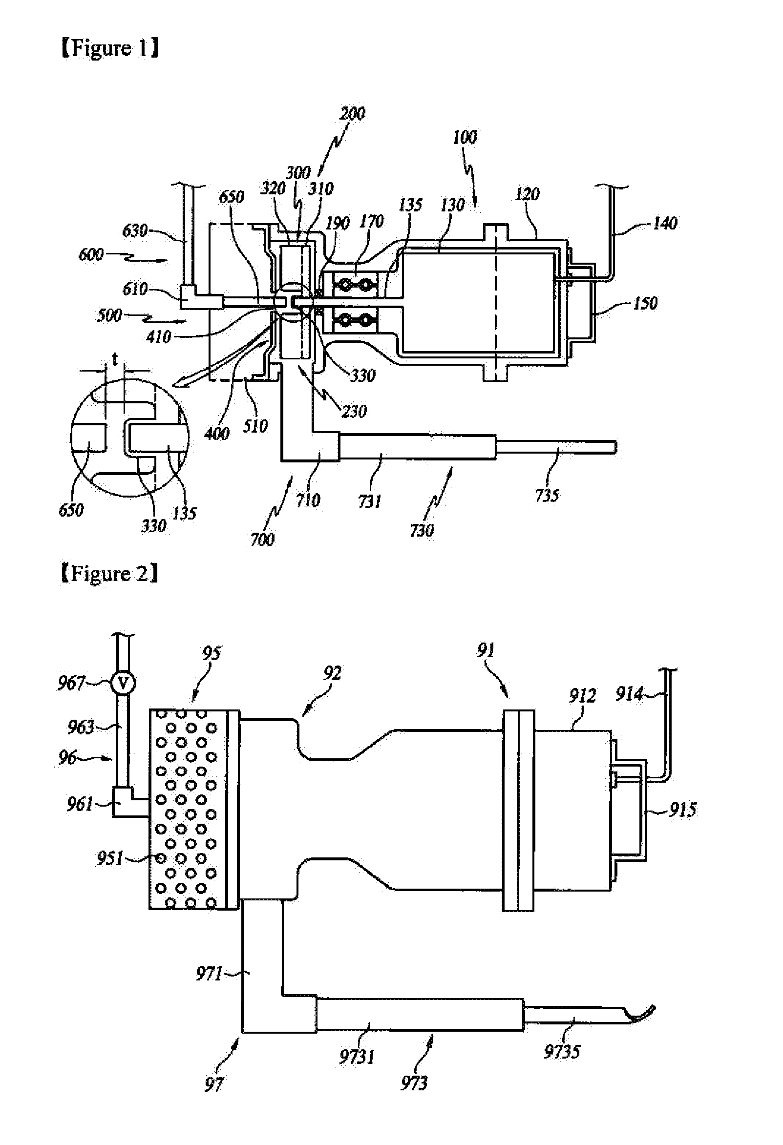
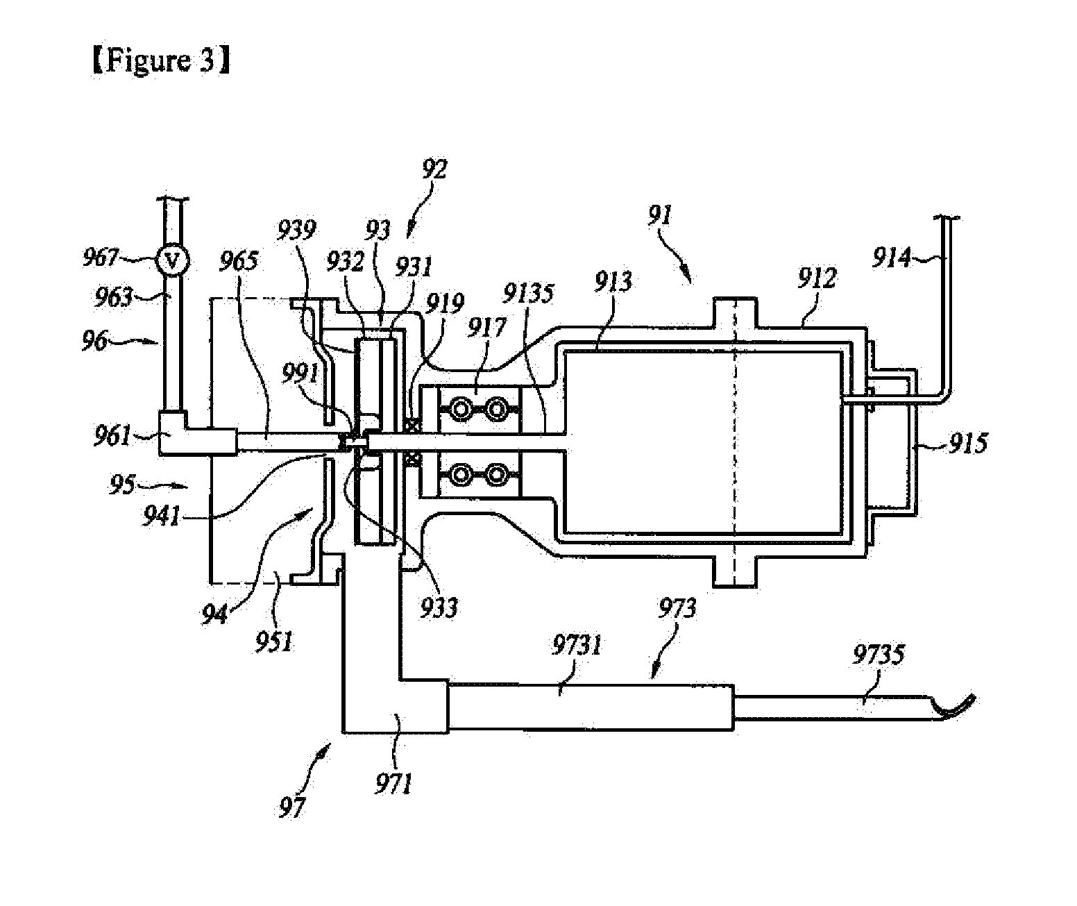
[0067]As shown in FIGS. 2 to 4 and FIG. 29, an aeration device according to the present invention is installed under water to introduce external air, mix the external air with water, and discharge the mixed air and water, and the aeration device includes a hollow casing 91, a mixing unit 92 formed on the front side of the casing 91, an impeller 93 located inside the mixing unit 92, a separator plate 94 located on the front side of the mixing unit 92, an intake housing 95 located in front of the separator plate 94, an air inflow unit 96 extended toward the mixing unit 92 to pass through the intake housing 95 and serving as an air inflow passage, a discharge unit 97 communicating with the mixing unit 92 to discharge the water and air mixed with each other, and an auxiliary intake unit 99 located on the front side of the impeller 93 in such a manner as to be rotated unitarily with a driving shaft 135 of a motor 130.

[0068]The air inflow unit 96 includes a portion extended in the longitu...

second embodiment

[0114]According to the present invention, the aeration device further includes an air adjusting valve 967 mounted on the air inflow unit 96. The air adjusting valve 967 is mounted on the air inflow unit 96, and in more detail, it is mounted on an inflow pipe 963. Of course, the air adjusting valve 967 may be mounted on an inflow tap 961 or an extension pipe 965, but desirably, it is mounted on the inflow pipe 963. The air adjusting valve 967 serves to control an amount of air introduced through the air inflow unit 96. The formation of the air adjusting valve 967 enables the amount of air introduced through the inflow pipe 963 to be controlled, thus efficiently conducting the aeration operation.

[0115]According to the second embodiment of the present invention, as shown in FIGS. 25 to 28, the aeration device further includes a mixing accelerating unit 939.

[0116]The mixing accelerating unit 939 is located in front of the impeller 93 and fixedly coupled to the front end surfaces of rota...


PUM

PropertyMeasurementUnit
depthaaaaaaaaaa
depthaaaaaaaaaa
sectional area reduction rateaaaaaaaaaa

Abstract

Aeration device includes a hollow casing having a motor therein; a mixing unit formed on front side of the casing and having a discharge hole formed in radial direction and an intake hole formed on front thereof; an impeller located inside the mixing unit and coupled to a driving shaft of the motor, the driving shaft extended to the mixing unit, so as to be rotated with the driving shaft, to generate flow in outward radial direction upon rotation, an air inflow unit having one side end located in front of the impeller and serving as an air inflow pipe for introducing air to the mixing unit; and an auxiliary intake unit located on front side of the impeller to be rotated with the driving shaft of the motor and inserted into the air inflow unit to allow fluid in the air inflow unit to flow backward upon rotation.

Description

TECHNICAL FIELD[0001]The present invention relates to an aeration device, and more particularly, to an aeration device that is capable of aerating wastewater upon organic wastewater treatment to increase an amount of dissolved oxygen, thus improving wastewater treatment efficiencies.BACKGROUND ART[0002]Generally, wastewater is aerated in organic wastewater treatment using microorganisms. If the wastewater is aerated, the amount of dissolved oxygen of the wastewater is increased to activate aerobic microorganisms and further to accelerate the removal of suspended materials and harmful gas, thus raising wastewater treatment efficiencies. Even the water in a tank of a fish farm is aerated, and in this case, an amount of dissolved oxygen is increased to prevent the water from being contaminated and further to help the growth of live fish. Further, the aeration prevents water bloom and red tide from occurring.[0003]A conventional aeration device is disclosed in Korean Patent Registration...

Claims


Application Information

Patent Timeline
Patent Type & Authority Applications(United States)
IPC IPC(8): C02F3/12B01F25/64
CPCC02F3/1278C02F7/00C02F2201/002Y02W10/10B01F23/2332B01F27/25F01D5/16B05B1/28B01F23/2331B01F23/23351B01F23/23353B01F23/23366B01F23/23367
Inventor JANG, SUN WONJEONG, JIN II
Owner JANG SUN WON
Why Eureka
Try Eureka