System, method & computer program product

a technology of system and computer program, applied in the field of lubrication system, can solve problems such as machine breakdown and component service life, and achieve the effects of minimizing friction and wear, optimizing component and machinery service life, and reducing cost and complexity of control uni

Active Publication Date: 2016-07-21
OSAKEYHTIO SKF
View PDF2 Cites 13 Cited by
  • Summary
  • Abstract
  • Description
  • Claims
  • Application Information

AI Technical Summary

Benefits of technology

[0008]Additionally, components such as pressure switches / gauges and transmitters, flow meters, volumetric meters, differential pressure switches and piston detectors are not required to monitor and control the lubrication system, thereby reducing the cost and complexity of the control unit needed for monitoring the lubrication system. Furthermore, it is possible to determine from the current shape minimum / maximum relationship that the output is lubricant and not air.
[0009]A lubrication system according to the present invention may be used for any industrial application to provide the appropriate lubrication quantity at the correct intervals, thereby minimizing friction and wear and optimizing component and machinery service life. The lubrication system provides proper, precise lubricant replenishment to all required points, enabling significant savings in repair and spare costs, increased machine reliability, savings in lubricant costs due to accurate timing and dosing of lubricants, fewer shutdowns and production losses, reduced environmental impact and greater safety for workers.

Problems solved by technology

Over- or under-lubrication can namely negatively influence a machine component's service life and may result in machine breakdown.

Method used


Image

  • System, method & computer program product
  • System, method & computer program product
  • System, method & computer program product

Examples


Embodiment Construction

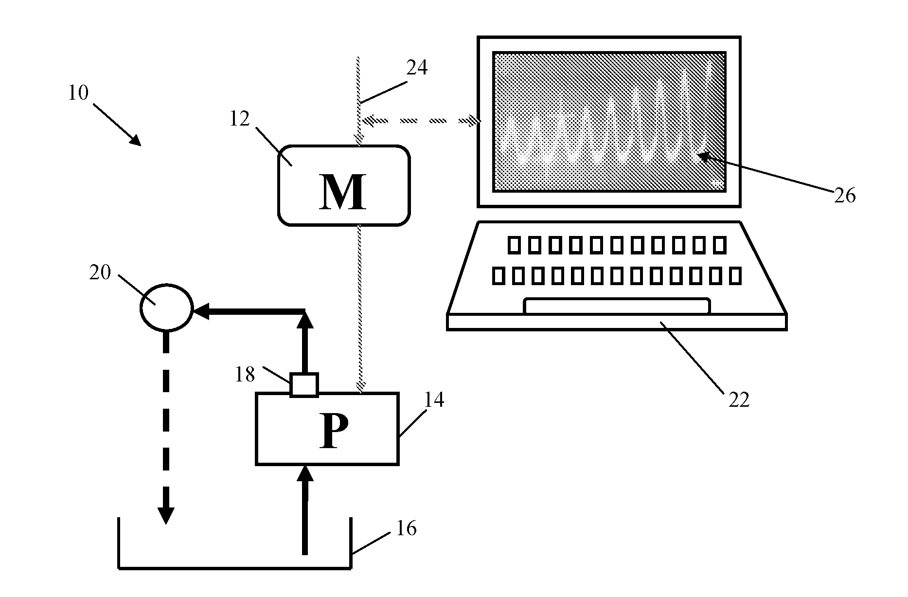
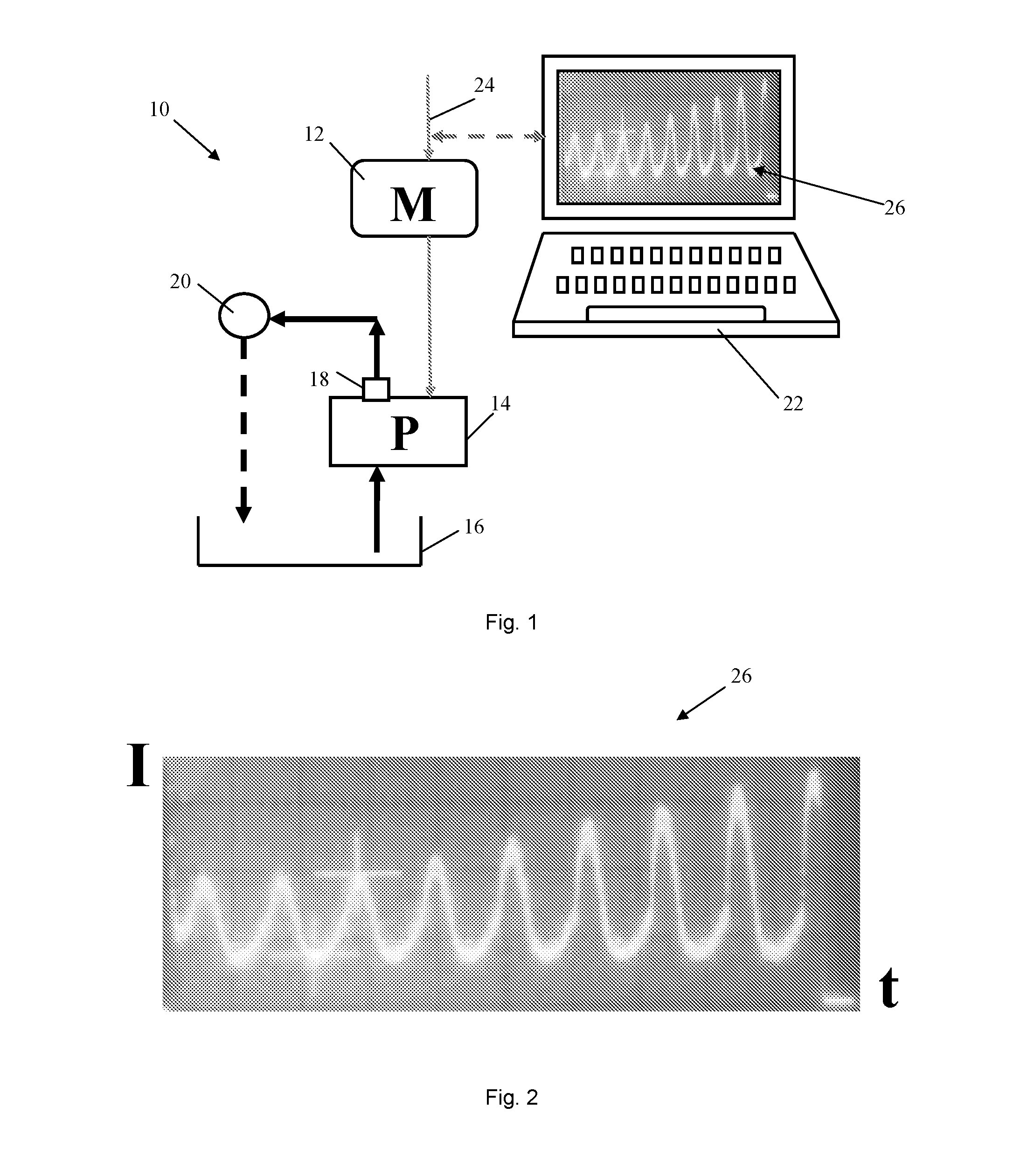
[0025]FIG. 1 shows a lubrication system 10 comprising a motor 12, a positive displacement pump 14 driven by the motor 12, a lubricant container 16 in fluid communication with the positive displacement pump 14 and a lubricant outlet 18 in fluid communication with the lubricant container 16. The motor 12 is a DC electric motor. The fluid container 16 can be arranged to store lubricant directly or to receive lubricant-filled cartridges.

[0026]The positive displacement pump 14 is arranged to carry out at least one discharge stroke to dispense lubricant from the lubricant outlet 16 when the lubrication system 10 is in use. The lubricant dispensed from the lubricant outlet 16 lubricates a lubricant point 20. In circulation lubrication systems, lubricant may then be returned to the lubricant container 16 although this will not be the case in total loss lubrication systems. The lubrication system 10 comprises a control unit 22 that is arranged to determine the amount of lubricant that is dis...


PUM


Abstract

A lubrication system comprising a motor, a positive displacement pump driven by the motor, a lubricant container in fluid communication with the positive displacement pump and at least one lubricant outlet in fluid communication with the lubricant container. The positive displacement pump is arranged to carry out at least one discharge stroke to dispense lubricant from the at least one lubricant outlet when the lubrication system is in use. The lubrication system also comprises a control unit that is arranged to determine an amount of lubricant that is dispensed from the lubricant container via the at least one lubricant outlet when the lubrication system is in use. The control unit is arranged to monitor current supplied to the motor to obtain a motor current signal, and to determine a number of the discharge strokes from the motor current signal.

Description

CROSS REFERENCE TO RELATED APPLICATION[0001]This is a Non-Provisional Patent Application, filed under the Paris Convention, claiming the benefit of Sweden (SE) Patent Application Number 1550049-9, filed on 21 Jan. 2015 (Jan. 21, 2015), which is incorporated herein by reference in its entirety.TECHNICAL FIELD[0002]The present invention concerns a lubrication system comprising a control unit that is arranged to determine the amount of lubricant that is dispensed from the lubricant system when it is in use. The present invention also concerns a method and a computer program product for determining the amount of lubricant that is dispensed from such a lubricant system when it is in use.BACKGROUND OF THE INVENTION[0003]Lubrication systems perform the task of supplying individual lubrication points or a group of lubrication points, such as at least one part of a bearing, joint, gear, and / or any other part(s) of one or more machines with a varying or non-varying amount of exactly metered l...

Claims


Application Information

Patent Timeline
Patent Type & Authority Applications(United States)
IPC IPC(8): F16N29/02H02P7/00F16N21/00F16N13/00F16N19/00
CPCF16N29/02F16N13/00H02P7/00F16N21/00F16N19/00F16N13/06F16N29/00F16N2013/063F16N2250/40F04B49/065F16N7/38F16N13/22F16N2270/20
Inventor MOILANEN, RISTO
Owner OSAKEYHTIO SKF
Why Eureka
Try Eureka